Traction control device

Inactive Publication Date: 2008-12-30
ADVICS CO LTD
View PDF33 Cites 2 Cited by
  • Summary
  • Abstract
  • Description
  • Claims
  • Application Information

AI Technical Summary

Benefits of technology

[0007]It is an object of the present invention to curb unnecessary execution of a traction control when a vehicle is stopped.
[0009]As described above, the engine speed is detected, and racing noise is assumed as affecting a wheel speed of a drive wheel detected by a wheel speed detection mechanism when the engine speed exceeds the predetermined speed. Therefore, a traction control is not initiated, making it possible to prevent unnecessary execution of the traction control based upon racing noise when the vehicle is stopped.
[0017]More specifically, among the wheel speeds calculated every predetermined control cycle in the wheel speed detection mechanism, in cases where an absolute value of a difference between a current wheel speed newly calculated and a previous wheel speed previously calculated is equal to or greater than a predetermined value, and an absolute value of a difference between the previous wheel speed and a wheel speed before the previous wheel speed, which is calculated prior to the previous wheel speed, is equal to or greater than the predetermined value, the wheel speed before the previous wheel speed is set as a new wheel speed. Thus, it is possible to stop reduction of the driving force by the driving force reduction mechanism.

Problems solved by technology

Therefore, the brake ECU obtains an erroneous detection result indicating that the wheel is rotating, despite the stopped state of the vehicle, from the detection signal of the wheel speed sensor affected by noise.
A problem arises when the brake ECU executes traction control based upon this erroneous detection.
In such cases where the traction control is unnecessarily executed, for example, when the engine output is lowered through an engine control, the engine does not race, despite the attempt to make it do so.

Method used


Image

  • Traction control device
  • Traction control device
  • Traction control device

Examples


first embodiment

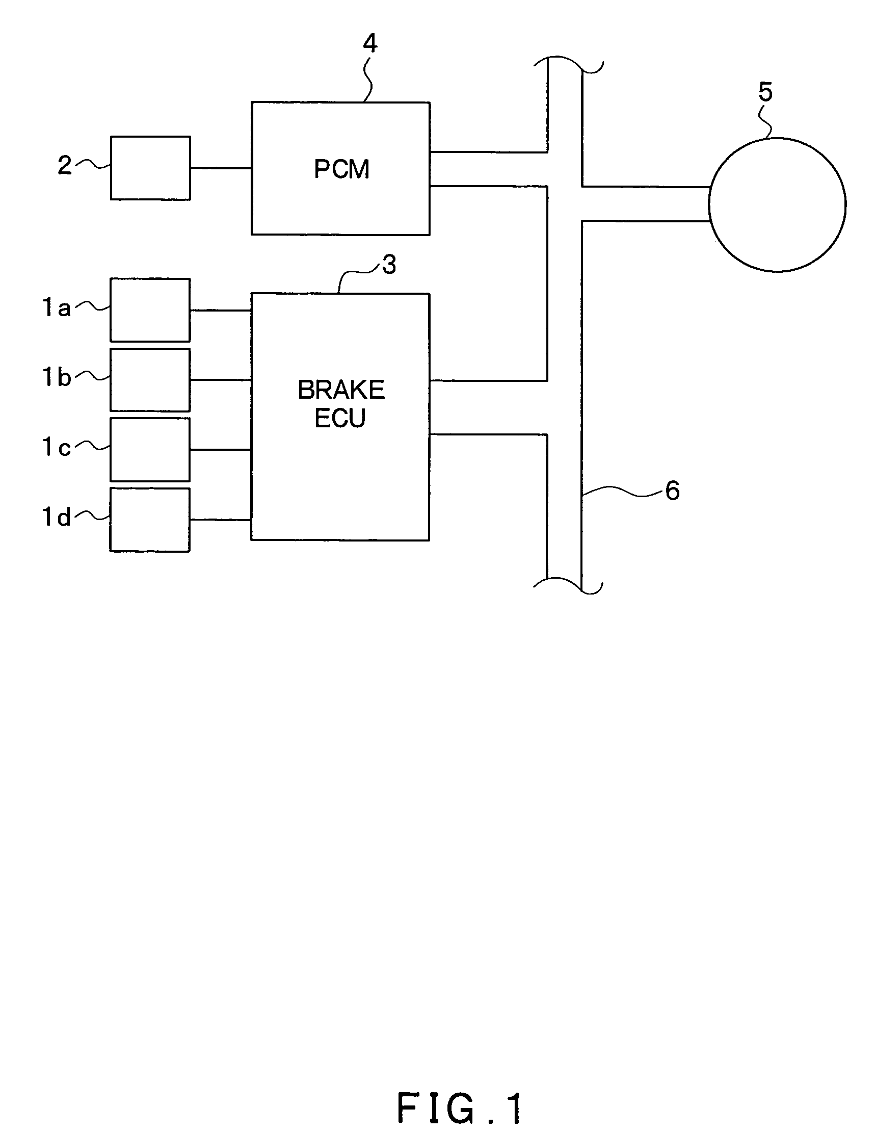
[0025]FIG. 1 is a block diagram of a traction control system to which an embodiment of the present invention is applied.

[0026]A traction control system according to a first embodiment of the present invention will be explained with reference to this drawing.

[0027]The traction control system includes a brake ECU 3 for an ABS control and a traction control in order to drive an ABS actuator and various sensor groups 1a-1d and 2 installed in a vehicle, a PCM 4 for controlling engine output, a traction control operation lamp 5, and a serial communication line 6 for connecting these structures.

[0028]Wheel speed sensors 1a-1d and an engine speed sensor 2 form the various sensor groups 1a-1d and 2.

[0029]The wheel speed sensors 1a-1d are installed in wheels mounted on a vehicle. Furthermore, a plurality of the wheel speed sensors 1a-1d are configured to output corresponding pulse signals serving as wheel speed signals for each wheel. Each wheel speed signal is used in calculations such as th...


PUM


Abstract

A newly obtained wheel speed of a drive wheel is not used in a calculation for acceleration slip when a vehicle is stopped, for example, when the wheel speed of a rolling wheel is zero and an engine speed is high. A wheel speed calculated before a previous wheel speed is, for example, set as a current wheel speed. In this manner, even if the wheel speed of a driving wheel is due to the effect of racing noise, it is possible to limit erroneous determinations that indicate acceleration slip is being generated, based upon such a wheel speed. In addition, unnecessary execution of a traction control can also be curbed.

Description

CROSS REFERENCE TO RELATED APPLICATION[0001]This application is based upon and claims the benefit of Japanese Patent Application No. 2003-331484 filed on Sep. 24, 2003, the content of which are incorporated herein by reference.FIELD OF THE INVENTION[0002]The present invention relates to a traction control device capable of suppressing acceleration slip of a wheel generated during acceleration of a vehicle.BACKGROUND OF THE INVENTION[0003]There are traction control devices (refer to Japanese Patent Laid-Open Publication No. 05-86920 for an example) in which the acceleration slip of wheels is detected based upon the detection output from respective wheel speed sensors installed in an ABS (anti-skid brake system). Thus, the acceleration slip is suppressed by the traction control devices.[0004]In such traction control devices, for example, a brake ECU for controlling an ABS actuator receives detection signals from each wheel speed sensor, as well as detection signals sent from a vehicle...

Claims


Application Information

Patent Timeline
Patent Type & Authority Patents(United States)
IPC IPC(8): B60T7/12G05D1/00G06F17/00G06F7/00B60T8/175B60K28/16B60T8/58F02D29/02
CPCB60K28/16B60T8/175B60W2520/263B60W2520/28
Inventor TSURUHARA, RYUZOINOUE, YASUMI
Owner ADVICS CO LTD
Why Eureka
Try Eureka