Vehicle attitude control device based on stability factor

a technology of stability factor and attitude control, which is applied in the direction of steering initiation, instruments, vessel construction, etc., can solve the problems of reducing the actual stability factor of the vehicle, affecting the operation of the vehicle, so as to prevent unnecessary execution of attitude control and reduce the sensitivity

Inactive Publication Date: 2010-01-12
ADVICS CO LTD
View PDF22 Cites 11 Cited by
  • Summary
  • Abstract
  • Description
  • Claims
  • Application Information

AI Technical Summary

Benefits of technology

[0014]Accordingly, it is a primary object of the present invention to provide an improved vehicle attitude control device which is capable of preventing the unnecessary execution of an attitude control for a vehicle reliably by lowering the sensitivity in judging whether the attitude control is to be executed, in dependence on the result of a comparison between an estimated stability factor and a reference stability factor, so that the attitude control can be executed appropriately despite of the variation in the stability factor.

Problems solved by technology

However, in the aforementioned vehicle turning control device, although the estimated stability factor is calculated on the basis of a stable turning motion, it has the possibility of differing from the actual stability factor of the vehicle.
In addition, since the estimated stability factor is large than the actual stability factor, the target yaw rate tends to decrease excessively.
Accordingly, it is likely that the oversteer control is executed by mistake notwithstanding that the vehicle is in a state that the oversteer control (the OS control) should not be executed.
In addition, since the estimated stability factor is smaller than the actual stability factor, the target yaw rate increases excessively.
Accordingly, it is likely that the understeer control is executed by mistake notwithstanding that the vehicle is in a state that the understeer control (the US control) should not be executed.
In any case, in the domains A4 to A9, it is likely that the attitude control is executed excessively (more than as needed).

Method used


Image

  • Vehicle attitude control device based on stability factor
  • Vehicle attitude control device based on stability factor
  • Vehicle attitude control device based on stability factor

Examples


first embodiment

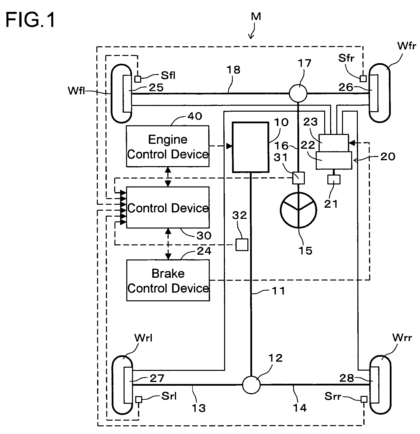
[0034]A vehicle attitude control device in the first embodiment according to the present invention will be described hereinafter with reference to FIG. 1. The vehicle attitude control device is applied to a vehicle M of the rear drive type provided with a vehicle brake device 20 which is capable of applying brake forces independently to left and right front wheels Wfl, Wfr and left and right rear wheels Wrl, Wrr of the vehicle.

[0035]The vehicle M is provided with an engine 10 which is incorporated longitudinally at the front of a vehicle body. The engine 10 is connected to the left and right rear wheels Wrl, Wrr through a propeller shaft 11, a differential gear 12, and left and right rear axle shafts 13 and 14, whereby the left and right rear wheels Wrl, Wrr are driven by the output torque of the engine 10. Moreover, the vehicle M is provided with a steering wheel (handle) 15 manipulated by the driver. The handle 15 is connected to a steering shaft 16 integrally. The steering shaft ...

second embodiment

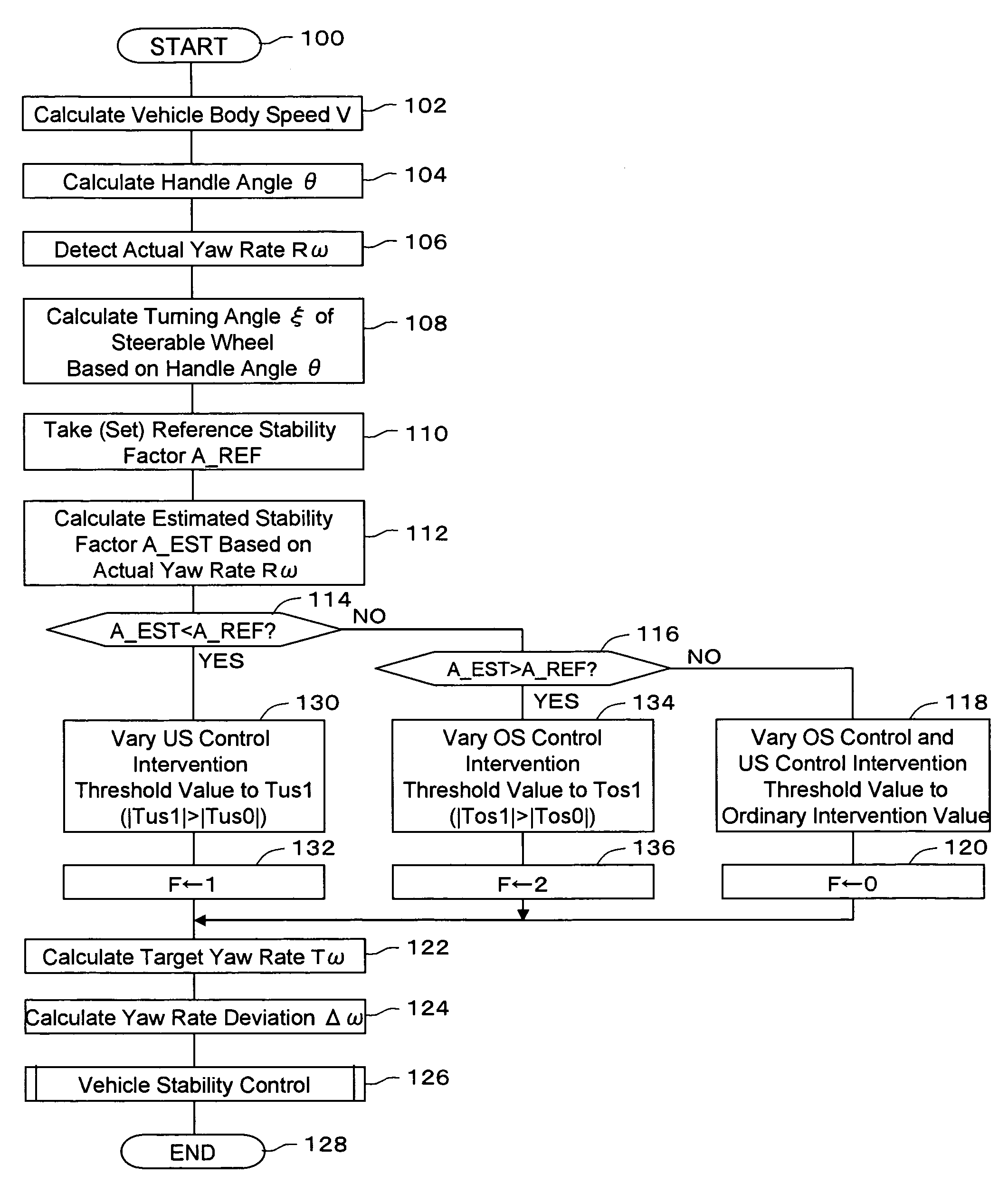
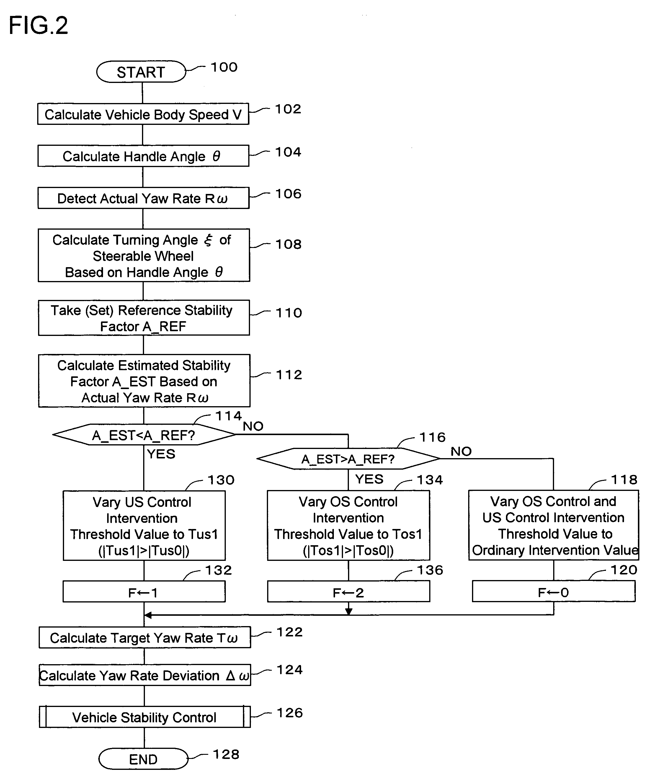
[0091]Next, a vehicle attitude control device in a second embodiment according to the present invention will be described with reference to drawings. In the foregoing first embodiment, the control device 30 compares the yaw rate deviation Δω derived based on the stability factor with the US control intervention threshold value Tus and the OS control intervention threshold value Tos which are the control intervention threshold values, to execute the attitude control for the vehicle in dependence on the result of such comparison. The attitude control necessary-or-not judgment sensitivity is varied by varying the control intervention threshold value based on the result of the comparison between the estimated stability factor A_EST and the reference stability factor A_REF. On the other hand, in the second embodiment, the control device 30 varies the attitude control necessary-or-not judgment sensitivity by compensating the stability factor based on the result of the comparison between t...


PUM


Abstract

A vehicle attitude control device derives a stability factor during turning of a vehicle based on the behavior of the vehicle to take the derivation result as an estimated stability factor (step 112), compares the estimated stability factor with a reference stability factor (steps 114 and 116), varies an attitude control necessary-or-not judgment sensitivity based on the comparison result (steps 118, 130 and 134), and executes the attitude control for the vehicle (step 126).

Description

[0001]This application claims priority under 35 U.S.C. 119 with respect to Japanese Application No. 2004-207153 filed on Jul. 14, 2004.BACKGROUND OF THE INVENTION[0002]1. Field of the Invention[0003]The present invention relates to a vehicle attitude control device.[0004]2. Discussion of the Related Art[0005]Heretofore, as vehicle attitude control devices of this kind, there has been known a vehicle turning control device which is provided with wheel speed sensors, a steering wheel angle sensor, a yaw rate sensor and the like (refer to Patent Document 1). In this vehicle turning control device, an arithmetic circuit 58 in an ECU 28 calculates a target yaw rate γt to control a yawing moment based on each of detection values which are detected by those various sensors 50. A control circuit 64 controls a controlled object 70 (automatic brake system) so that the detected actual yaw rate γ coincides with the target yaw rate γt. In the arithmetic circuit 58, an operation section 58b calcu...

Claims


Application Information

Patent Timeline
Patent Type & Authority Patents(United States)
IPC IPC(8): B62D6/00B60R16/02B60T8/172B60T8/1755B60W10/04B60W10/06B60W10/18B60W10/188B60W30/02B60W30/045B60W40/10
CPCB60T8/1755B60W10/06B60W10/184B60W30/045B60W40/11B60W40/112B60W40/114B60W2510/20B60W2520/10B60W2520/14B60W2540/18
Inventor KATAYAMA, YOSHIO
Owner ADVICS CO LTD
Why Eureka
Try Eureka