Electrical plug assembly with bi-directional push-pull actuator

a technology of electric plugs and actuators, which is applied in the direction of electrical apparatus, connection, coupling device connection, etc., can solve the problems of difficult use of plugs in certain spaces, difficult grasping and pulling the handle of plugs to unlatch the latch with the receptacle, and difficult to switch between pushing and pulling the handles of plugs

Inactive Publication Date: 2009-01-06
TE CONNECTIVITY CORP
View PDF21 Cites 131 Cited by
  • Summary
  • Abstract
  • Description
  • Claims
  • Application Information

AI Technical Summary

Problems solved by technology

As a result, a user of the plugs cannot switch between pushing and pulling the handles of the plugs to latch the hooks.
The inability of existing plugs to permit unlatching the plugs with corresponding receptacles by only pushing or pulling the plug's handle (but not both) can make it difficult to use the plugs in certain spaces.
For example, the location of certain receptacles can make grasping and pulling the handle of a

Method used


Image

  • Electrical plug assembly with bi-directional push-pull actuator
  • Electrical plug assembly with bi-directional push-pull actuator
  • Electrical plug assembly with bi-directional push-pull actuator

Examples


Embodiment Construction

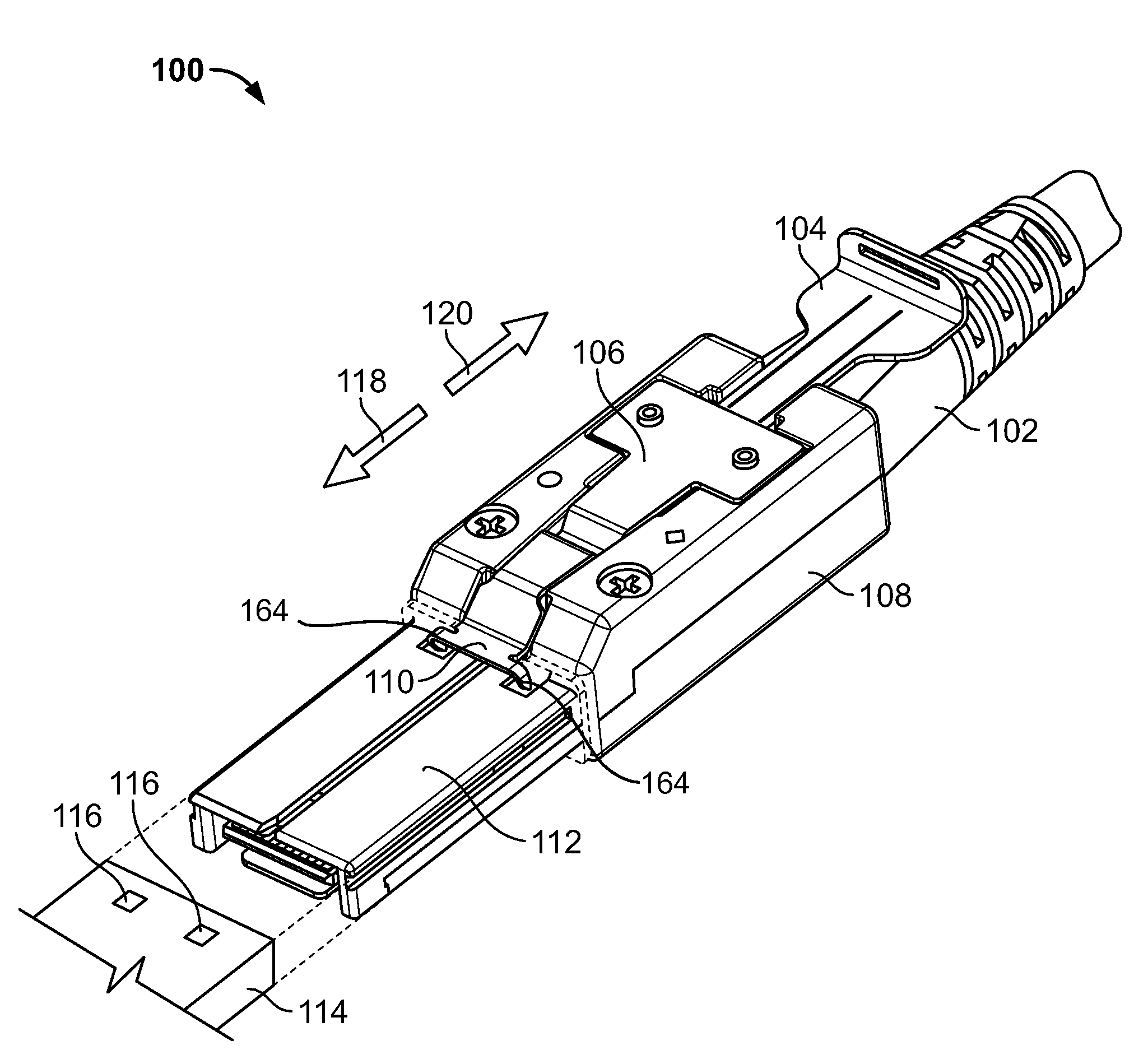
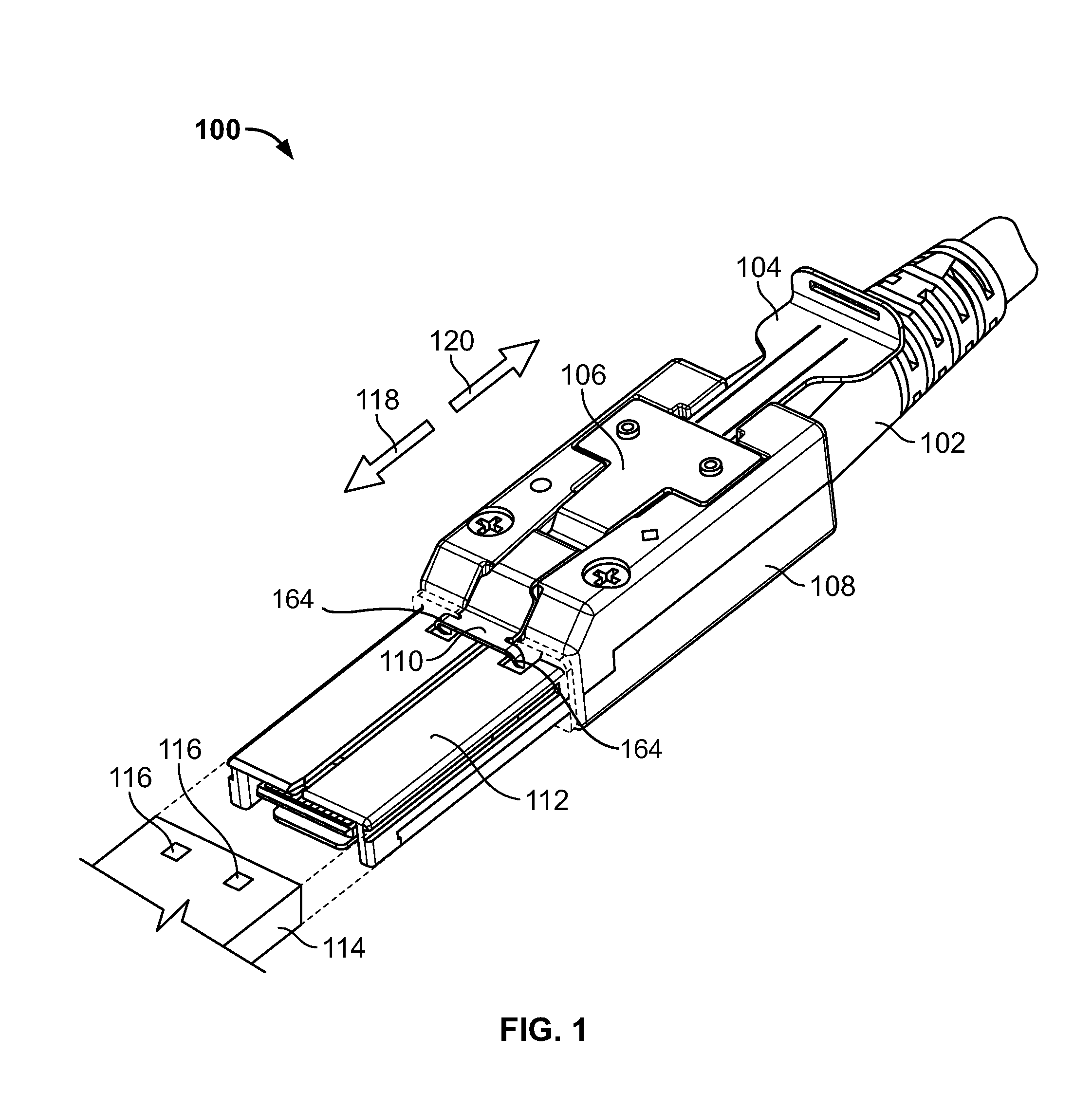
[0018]FIG. 1 is a perspective view of a bi-directional push / pull electrical plug assembly 100 formed according to one embodiment. The assembly 100 includes an actuator 104 located between a latch 106 and a housing 108. The housing 108 extends along a longitudinal direction and terminates in a mating end 112. The mating end 112 is configured to be inserted into a receptacle 114. A pair of hook elements 164 connected to a latching end 110 of the latch 106 latches with a pair of holes 116 in the receptacle 114 to secure the assembly 100 to the receptacle 114. A terminating end 102 of the housing 108 is provided at the end of a cable to communicate data from a device connected to the cable to the receptacle 114 via the plug assembly 100.

[0019]In operation, the actuator 104 may be moved in two diametrically opposed directions along the longitudinal axis of the housing 108. Specifically, the actuator 104 can be pushed in a push direction 118 and pulled in a pull direction 120 to raise the...


PUM


Abstract

An electrical plug assembly includes a housing, a latch and an actuator. The housing extends along a longitudinal axis and is configured to mate with a receptacle assembly. The latch is movably coupled to the housing and has a latching end configured to latch and unlatch the receptacle assembly. The actuator is interconnected with the housing and the latch. The actuator is movable in both a push direction and a pull direction. The actuator raises the latching end when the actuator is pushed along the longitudinal axis in the push direction. The actuator also raises the latching end when the actuator is pulled along the pull direction.

Description

BACKGROUND OF THE INVENTION[0001]The subject matter herein generally relates to plugs for electrical connectors and, more particularly, to an electrical connector plug having an actuator for operating a latch that secures the plug to a mating receptacle.[0002]Various types of plugs have been proposed for electrical connectors such as external mini-SAS connectors. The plugs are inserted into corresponding receptacles to communicate data. Existing plugs include a mating end that is plugged into the receptacle and hooks that fit into holes in the receptacle to securely hold the plug in the receptacle. The plug is unlatched from the receptacle by raising the hooks out of the holes in the receptacle and removing the plug.[0003]Existing plugs are configured to raise and lower the hooks of the plugs, relative to the receptacles, by actuating a tab or other handle on the plug. The hooks in some plugs are raised when the handle is pushed (referred to as “push-only plugs”).[0004]The hooks in ...

Claims


Application Information

Patent Timeline
IPC IPC(8): H01R13/627
CPCH01R13/6275H01R13/629
Inventor BRIANT, ERIC DAVIDWERTZ, JR., ROBERT HARRISONGORENC, DANIEL LEE
Owner TE CONNECTIVITY CORP
Why Eureka
Try Eureka