Knock sensor

a technology of knock sensor and sensor body, which is applied in the direction of rapid change measurement, instruments, measurement devices, etc., to achieve the effect of improving the workability of the knock sensor on the moun

Inactive Publication Date: 2009-01-13
NGK SPARK PLUG CO LTD
View PDF6 Cites 2 Cited by
  • Summary
  • Abstract
  • Description
  • Claims
  • Application Information

AI Technical Summary

Benefits of technology

[0005]The present invention addresses the above-mentioned problem. An advantage of the invention is a knock sensor that is fixed to an internal combustion engine by means of extending the fixing member through a through-hole formed in the support member, and which is capable of protecting the support member from being ground by the fixing member.
[0006]First embodiment of the present invention accomplishing the above-described purpose is a knock sensor comprising: a support member having a through-hole; a piezoelectric element held by the support member, wherein a fixing member extends through the through-hole and tightens the knock sensor from the upper face of the support member, while the bottom surface of the support member makes contact with an internal combustion engine; and a covering member fixed in a non-rotating state to the support member so that at least a part of the top surface of the support member may be covered, wherein the covering member is capable of preventing the fixing member from directly making contact with the top surface of the support member when the fixing member extends through the through-hole.
[0007]Therefore, such a knock sensor may protect the top surface of the support member from being ground or abraded by the fixing member, because the covering member covers the top surface of the support member. Further, since the covering member is fixed in a non-rotating state to the support member, the covering member is prevented from sliding on the support member when the fixing member is tightened. Thus, the support member is also protected from being abraded by the covering member.
[0008]In addition, the fixing member may be formed from two individual members: a member which extends through the through-hole; and a member which tightens up the knock sensor from the top surface of the support member, or by a combined member thereof. It is also contemplated that the knock sensor may include the covering member fixed to the support member.
[0009]The covering member of such a knock sensor is fixed to the support member so as not to come off therefrom when the knock sensor is fixed to a mounting portion of the internal combustion engine. As a result, the mounting workability of the knock sensor will be improved.
[0010]Further, the knock sensor preferably has a covering member that covers the entire top surface of the support member. Such a knock sensor would prevent the fixing member from directly making contact with the top surface of the support member. Furthermore, the support member may make even contact with the covering member which leads to a successful mounting of the knock sensor to the internal combustion engine.

Problems solved by technology

A problem with this type of knock sensor is that the sensor is connected to an internal combustion engine with a top surface of a support member in contact with a fixing material (bolt), whereby the top surface of the support member is ground, i.e., abraded, by the fixing member (bolt) when connected to the internal combustion engine.

Method used


Image

  • Knock sensor
  • Knock sensor
  • Knock sensor

Examples


Embodiment Construction

[0034]An embodiment of the present invention will be described below with reference to the drawings.

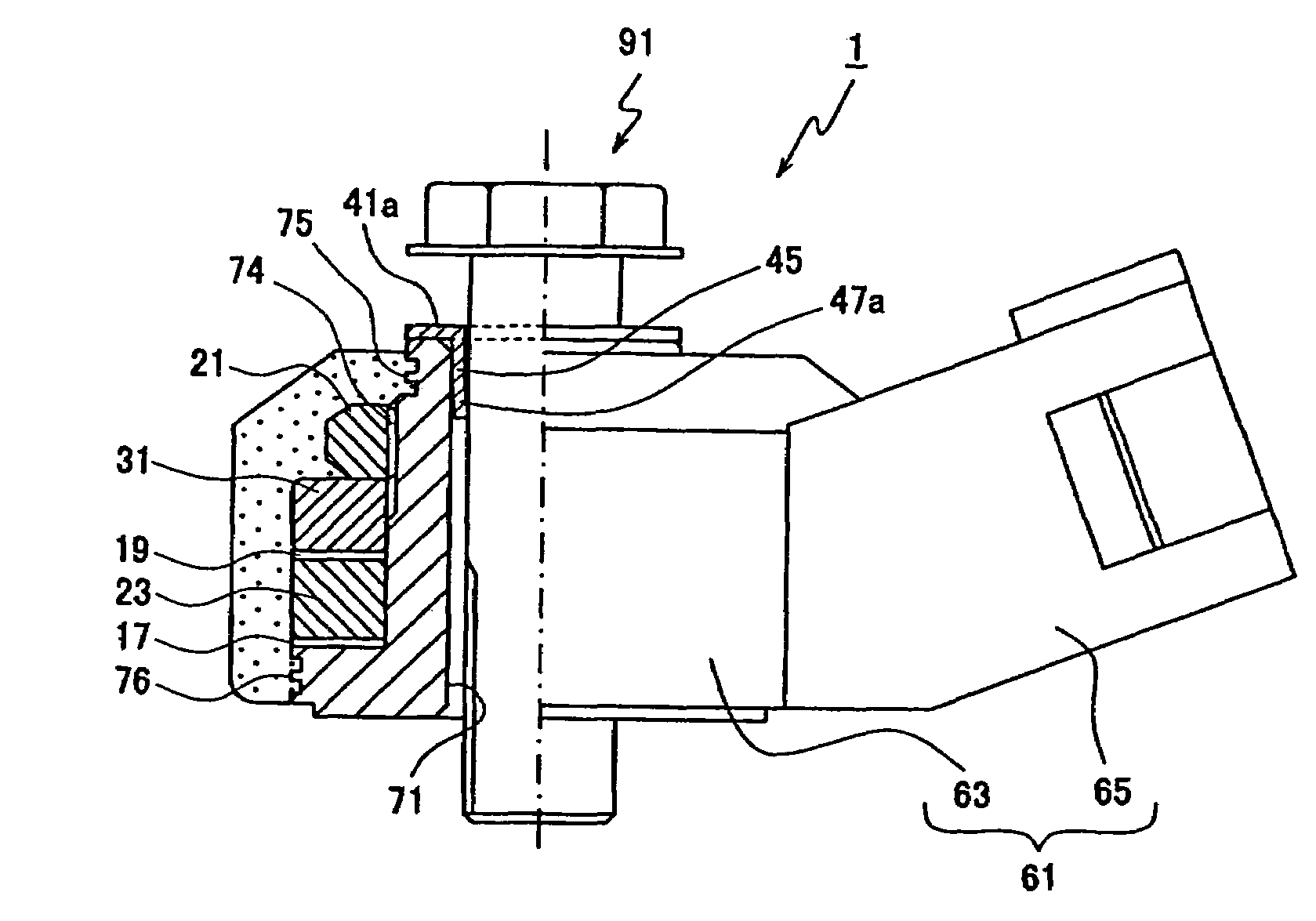
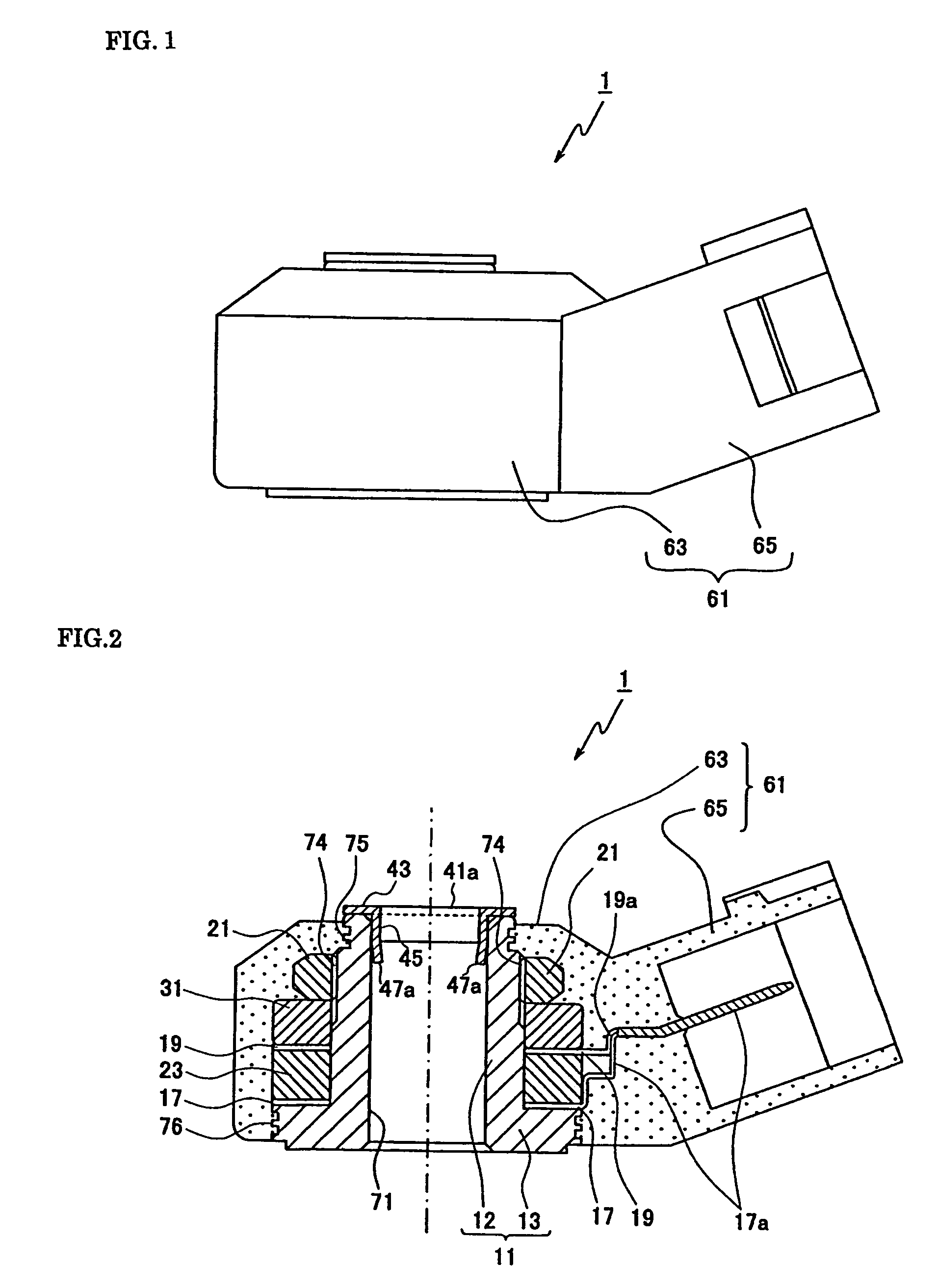
[0035]Referring first to FIG. 1, a non-resonance type knock sensor 1 according to the present invention (hereinafter referred to simply as knock sensor 1) is shown. FIG. 1 is an elevational view of a non-resonance type knock sensor 1.

[0036]A non-resonance type knock sensor 1 according to the present invention includes a casing 61 made of an insulation material (various types of resin material, such as PA (polyamide), which accommodates components, such as a piezoelectric element 23, therein.

[0037]The casing 61 includes a cylindrically shaped housing portion 63 whose upper side (the topside in FIG. 1, hereinafter called the upper side) is tapered and a connector portion 65 connected to an external device (e.g. ignition timing control unit). The connector portion 65 projects outwardly from an outer wall of the housing portion 63.

[0038]Referring now to FIG. 2, an internal structure of th...


PUM

PropertyMeasurementUnit
Young's modulus Eaaaaaaaaaa
diameteraaaaaaaaaa
Young's modulusaaaaaaaaaa

Abstract

A knock sensor 1 for attachment to an internal combustion engine. The knock sensor 1 includes a cap 41a and a support member 11. At least a part of the top surface of the support member 11 is covered by cap 41a to prevent a mounting bolt 91 from directly making contact with the top surface of the support member 11 when the mounting bolt 91 extends through a through-hole 71 in the sensor. The cap 41a covers the top surface of the support member 11 to protect the support member from being ground or abraded by the mounting bolt 91.

Description

FIELD OF THE INVENTION[0001]This invention relates to a knock sensor for detecting knocks caused in an internal combustion engine.BACKGROUND OF THE INVENTION[0002]A knock sensor is a device for detecting knocks caused in an internal combustion engine. Conventionally, a knock sensor is fixed to a mounting portion of an internal combustion engine by means of a fixing member, such as a bolt, which extends through a through-hole formed in a support member that supports a piezoelectric element (i.e. a sensor element).[0003]Japanese Patent Application Laid-open (kokai) No. 2004-85255 discloses a knock sensor having a support member made of a material, such as resin, having a relatively small Young's modulus to improve an output from the knock sensor.[0004]A problem with this type of knock sensor is that the sensor is connected to an internal combustion engine with a top surface of a support member in contact with a fixing material (bolt), whereby the top surface of the support member is g...

Claims


Application Information

Patent Timeline
Patent Type & Authority Patents(United States)
IPC IPC(8): G01L23/22
CPCG01H11/08G01L23/222
Inventor KUNO, HIROYUKIAOI, KATSUKIKONDO, NORIAKI
Owner NGK SPARK PLUG CO LTD
Why Eureka
Try Eureka