Illuminating system, device, and method for in-flight refueling

a technology for in-flight refueling and illumination systems, applied in aircrafts, rotorcraft, vehicles, etc., can solve the problems of affecting the vision of the operator of the second aircraft, the emission of lamps having a non-uniform illumination field, and the relatively short useful life of tungsten filament lamps of only 200-300 hours

Active Publication Date: 2009-01-13
THE BOEING CO
View PDF13 Cites 16 Cited by
  • Summary
  • Abstract
  • Description
  • Claims
  • Application Information

AI Technical Summary

Benefits of technology

[0011]Advantages provided by embodiments of the present invention may include, but are not limited to, the provision of eye-safe, covert illumination to illuminate an in-flight refueling operation between a first aircraft and a second aircraft, and the ability to adjust a breadth of an illumination area so as to tailor the illumination area to enclose an in-flight refueling position relative to the first aircraft without being unnecessarily large. Other advantages include providing such illumination from a generating device that provides emissions having predominantly a single wavelength that are both eye-safe and covert. Embodiments of the present invention also provide the advantage of providing a generating device that: is lightweight and durable, requires small amounts of power, and generates only small amounts of heat in providing illuminating emissions.

Problems solved by technology

However, in the disclosed illuminating systems, the lighting units used are tungsten filament lamps that produce emissions including large amounts of light in the visible wavelengths such that the illuminating system may hamper the vision of an operator of the second aircraft as it approaches the first aircraft for an in-flight refueling operation.
Also, the visible light emissions produced by the tungsten filament lamps are not covert, and may be visible to hostile observers and / or aircraft.
In addition, the tungsten filament lamps also have a relatively short useful life of only 200-300 hours and a large electrical power requirement.
The tungsten filament lamps also produce a large amount of heat and may require diffusing and filtered optics that result may result in the lamps' emissions having a non-uniform illumination field.

Method used


Image

  • Illuminating system, device, and method for in-flight refueling
  • Illuminating system, device, and method for in-flight refueling
  • Illuminating system, device, and method for in-flight refueling

Examples


Embodiment Construction

[0017]The present inventions now will be described more fully hereinafter with reference to the accompanying drawings, in which some, but not all embodiments of the invention are shown. Indeed, these inventions may be embodied in many different forms and should not be construed as limited to the embodiments set forth herein; rather, these embodiments are provided so that this disclosure will satisfy applicable legal requirements. Like numbers refer to like elements throughout.

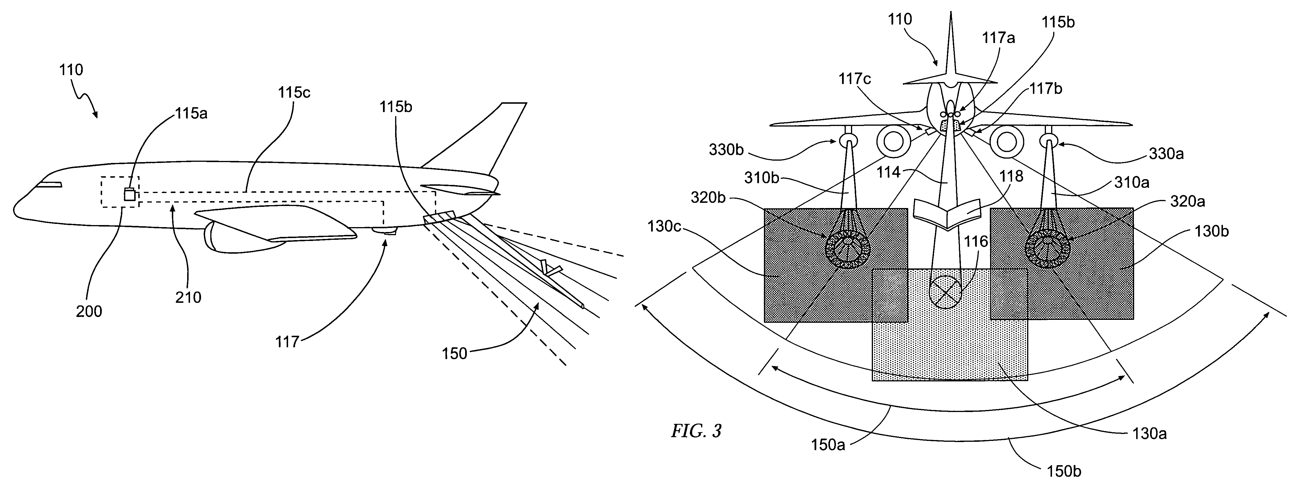
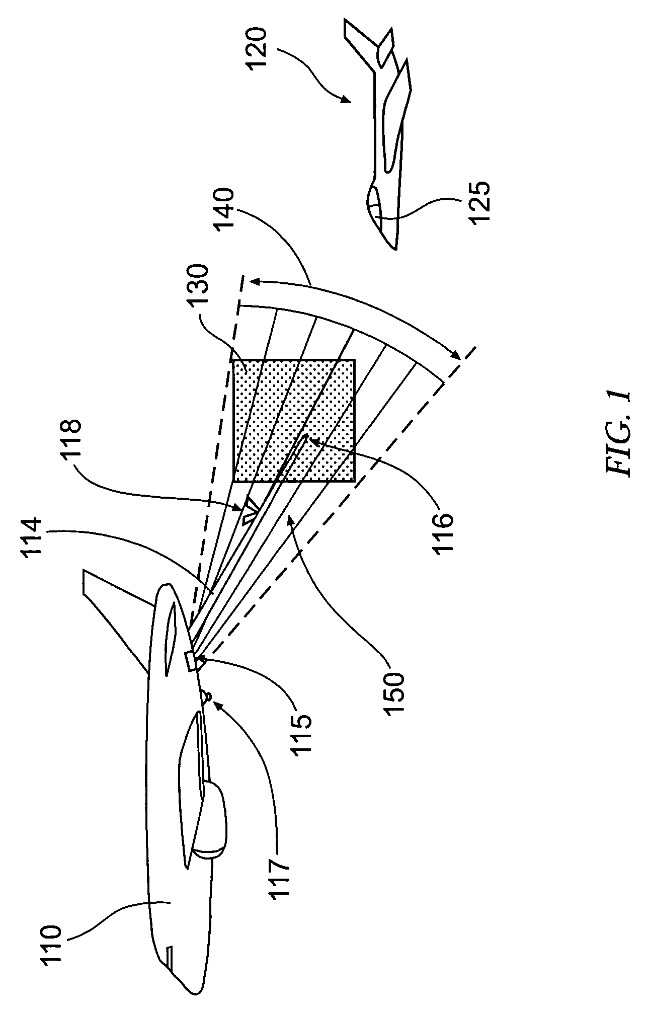
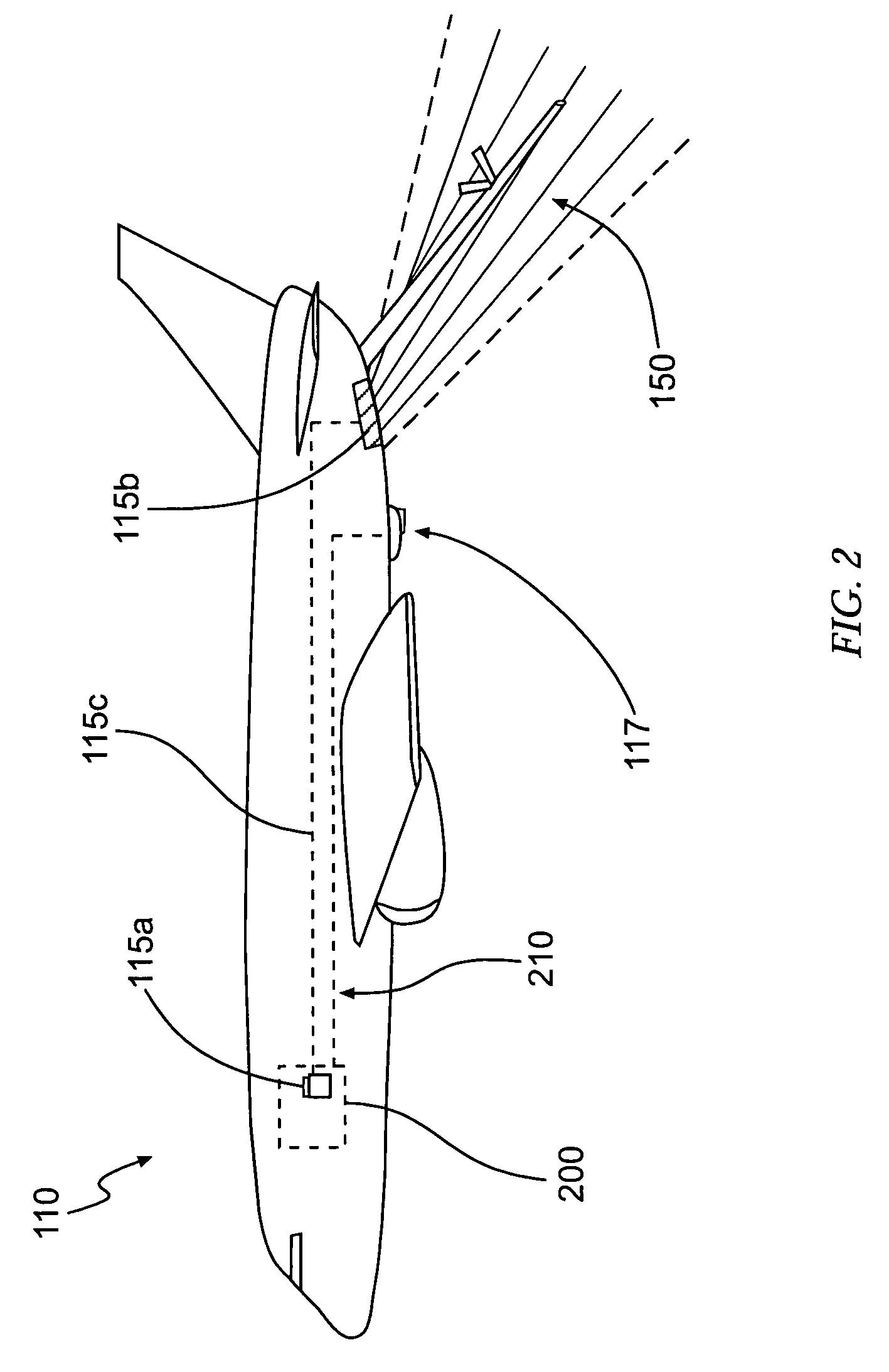
[0018]While the positioning system, device, and method embodiments of the present invention are described below in the context of in-flight refueling operations, involving a first aircraft 110 (serving as a tanker aircraft) and a second aircraft 120 (serving as a receiver aircraft), it should be understood that the embodiments of the present invention may also be utilized to illuminate a second aircraft approaching a position relative to a first aircraft for a variety of in-flight operations, including, but not...


PUM


Abstract

An illuminating system, device, and method are provided to illuminate an in-flight refueling operation involving a first aircraft, serving as a tanker aircraft and carrying the illuminating system of the present invention, and a second aircraft, entering an in-flight refueling position relative to the first aircraft. The system, device, and method of the present invention provide eye-safe, covert illumination suitable for illuminating the in-flight refueling position such that the second aircraft is illuminated upon entering the in-flight refueling position.

Description

FIELD OF THE INVENTION[0001]The present invention relates generally to in-flight refueling, and specifically, providing an illuminating system, device, and method for illuminating an in-flight refueling operation between a first and second aircraft. The system, device, and method of the present invention further provide a predominantly near infra-red emission having an emission envelope defined so as to contain an in-flight refueling position relative to the first aircraft so as to covertly illuminate the in-flight refueling operation.BACKGROUND OF THE INVENTION[0002]In-flight refueling (or air-to-air refueling) is an important method for extending the range of aircraft traveling long distances over areas having no feasible landing or refueling points. Although in-flight refueling is a relatively common operation, especially for military aircraft, precise positioning of a second aircraft (the receiver aircraft, for example) with respect to a first aircraft (the tanker aircraft, for ...

Claims


Application Information

Patent Timeline
Patent Type & Authority Patents(United States)
IPC IPC(8): B64D39/00B64D47/02
CPCB64D39/00B64D47/02B64C2027/8236B64D2203/00
Inventor HEWITT, GORDON S.SHOORE, JOSEPH DAVID
Owner THE BOEING CO
Why Eureka
Try Eureka