Control system for brake vacuum pump

a technology of control system and vacuum pump, which is applied in the direction of electric control, braking system, machines/engines, etc., can solve the problems of excessive and unfavorable operation of vacuum pump

Inactive Publication Date: 2009-01-13
SUBARU CORP
View PDF13 Cites 28 Cited by
  • Summary
  • Abstract
  • Description
  • Claims
  • Application Information

AI Technical Summary

Problems solved by technology

However, an arrangement that merely performs a driving control of the vacuum pump in response to a pressure state in the vacuum chamber as in the art disclosed in the above-described Japanese Unexamined Patent Application Publication No. 9-177678, may excessively operate the vacuum pump.
For example, when the negative pressure in the vacuum chamber temporarily becomes shallow (i.e., when the pressure becomes high) by a user performing repetitive braking operations in a short time, the vacuum pump may undesirably be operated even though the negative pressure can be quickly accumulated up to a predetermined value by using only the negative pressure occurring in the intake manifold.
Moreover, even in a situation not requiring so much braking force, such as before a starting state immediately after the startup of the engine, or in a constant running state at a relatively low speed, the vacuum pump may unfavorably be operated.

Method used


Image

  • Control system for brake vacuum pump
  • Control system for brake vacuum pump
  • Control system for brake vacuum pump

Examples


Embodiment Construction

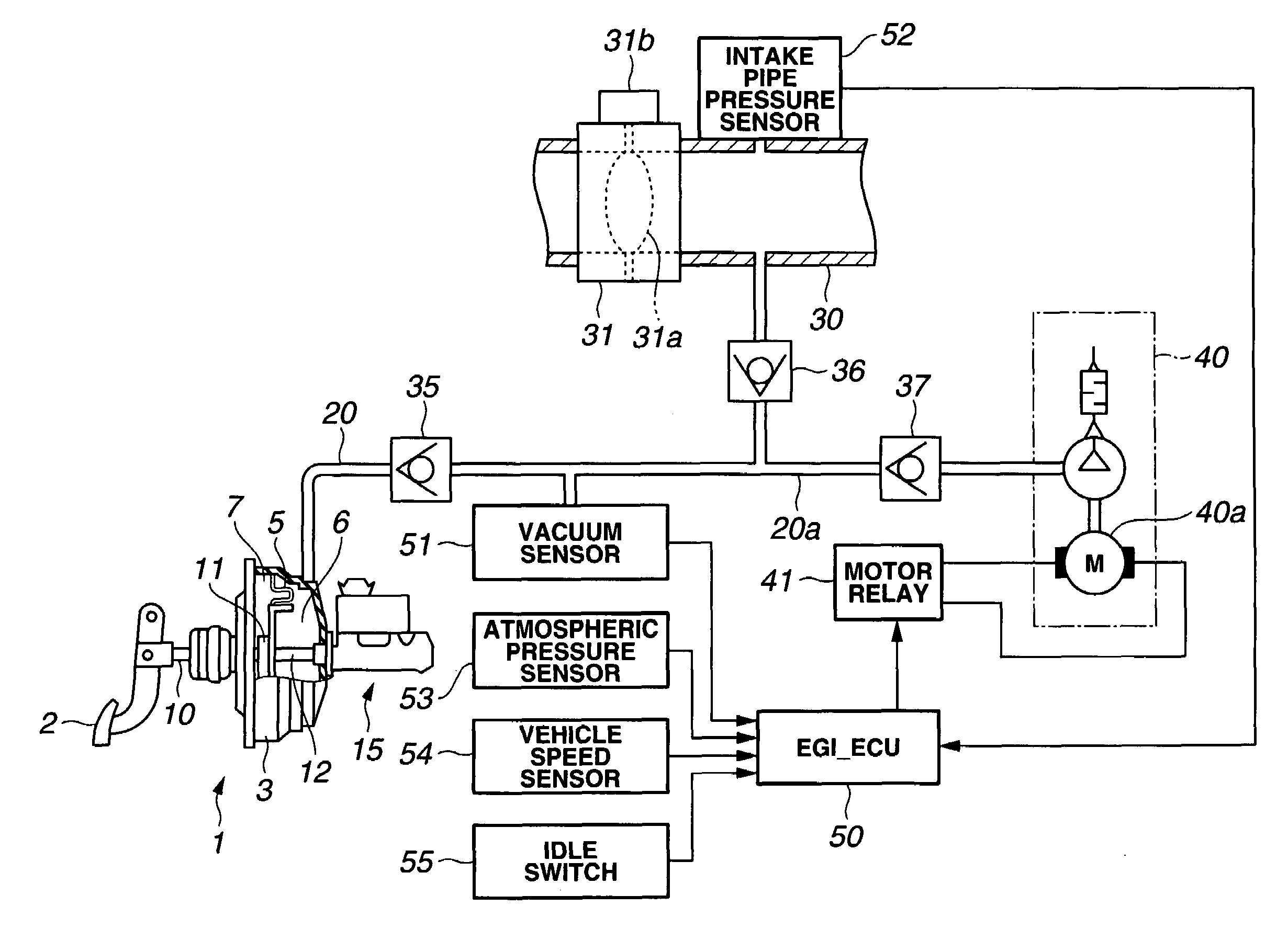
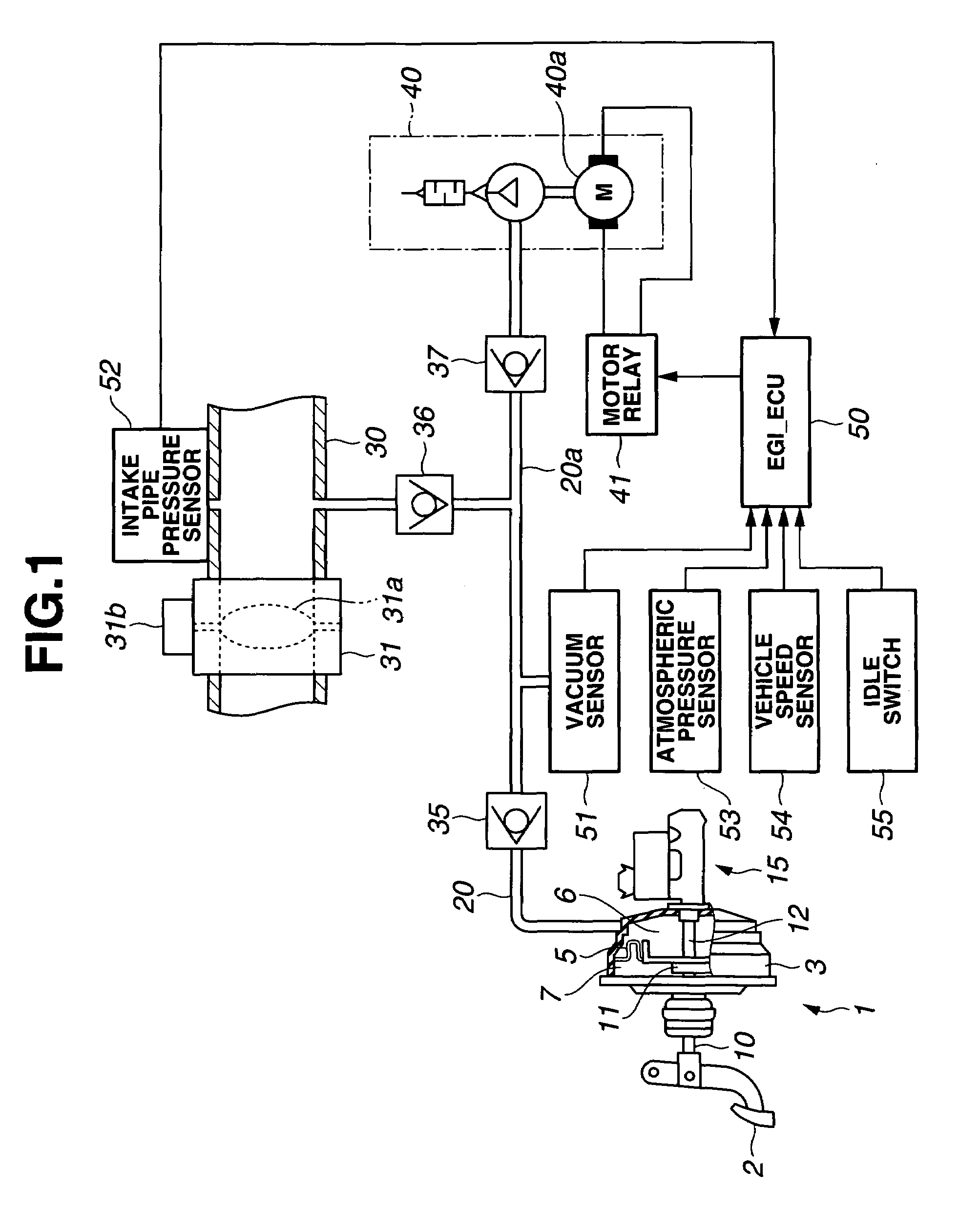
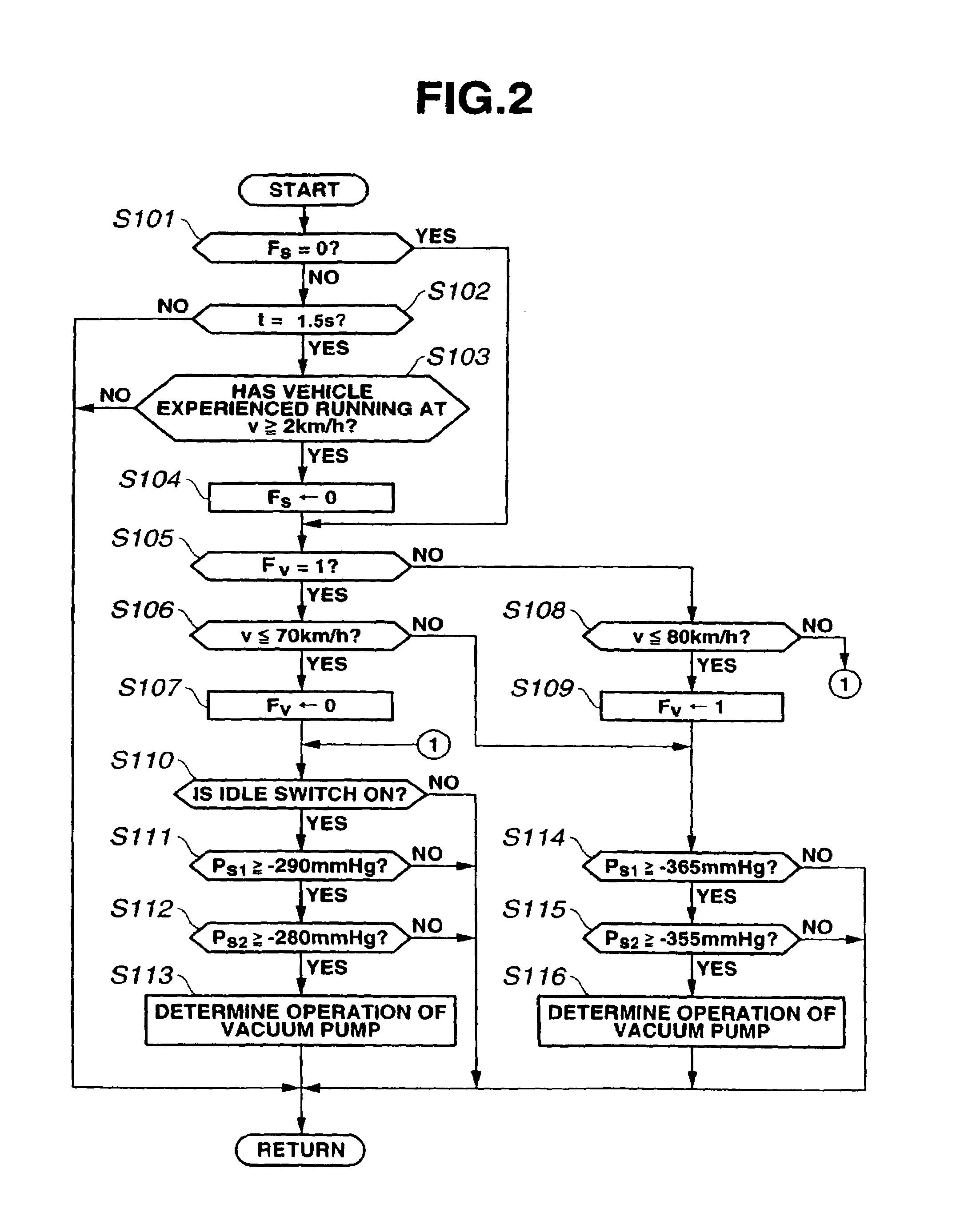
[0017]Hereinafter, the embodiment according to the present invention will be described with reference to the accompanying drawings. These drawings pertain to present embodiment. FIG. 1 is a schematic block diagram of a brake system, FIG. 2 is a flowchart showing an operation determination routine of a vacuum pump, FIG. 3 is a flowchart showing a driving control routine of the vacuum pump during low-speed running, and FIG. 4 is a flowchart showing the driving-control routine of the vacuum pump during high-speed running.

[0018]Referring to FIG. 1, a negative-pressure type brake booster 1 is for boosting the pedal force applied to a brake pedal 2. The brake booster 1 comprises a shell 3 fixed to a toe board or the like; a diaphragm 5 partitioning the shell 3 into a vacuum chamber 6 and a controlled pressure chamber 7; a control valve mechanism 11 fixed to the diaphragm 5 and controlling the communication and interruption between the vacuum chamber 6 and controlled pressure chamber 7 acc...


PUM


Abstract

A control system for a brake vacuum pump, the system being capable of accumulating a negative pressure required for a vacuum chamber, without excessively operating the vacuum pump. In this system, an EGI_ECU determines whether a vehicle has experienced running at a speed equal to or higher than a preset creep vehicle speed after the startup of an engine. The EGI_ECU prohibits the operation of the vacuum pump until the time when the vehicle experiences running at a speed equal to or higher than the creep vehicle speed. Thereby, in a situation obviously not requiring a strong braking force, such as in a stopped state immediately after the startup of the engine, the operation of the vacuum pump can be prohibited, which allows the vacuum pump to be accurately prevented from an unnecessary drive.

Description

CROSS REFERENCES TO RELATED APPLICATIONS[0001]The present invention claims benefit of Japanese Patent Application No. 2005-10888 filed on Jan. 18, 2005 and No. 2005-10889 filed on Jan. 18, 2005, the contents of which are incorporated by this reference.BACKGROUND OF THE INVENTION[0002]1. Field of the Invention[0003]The present invention relates to a control system for a brake vacuum pump, and more specifically, concerns a control system for the brake vacuum pump, the system performing the driving control of the vacuum pump that is connected to a vacuum chamber of a brake booster into which a negative pressure occurring in an intake manifold of an engine is introduced, and that assists the introduction of the negative pressure into the vacuum chamber.[0004]2. Description of the Related Art[0005]In a braking apparatus for a vehicle, the brake booster has been widely used for introducing the negative pressure occurring in the intake manifold of the engine into the vacuum chamber, and bo...

Claims


Application Information

Patent Timeline
Patent Type & Authority Patents(United States)
IPC IPC(8): B60T13/46
CPCB60K6/543B60T13/52B60T17/02F02D41/06F02D2200/0406F02D2250/41
Inventor ICHIKAWA, KATSUFUMI
Owner SUBARU CORP
Why Eureka
Try Eureka