

System, method, and apparatus for detecting a projected point on computer controlled displayed images
- Summary
- Abstract
- Description
- Claims
- Application Information
AI Technical Summary
Benefits of technology
Problems solved by technology
Method used
Image

Examples
first embodiment
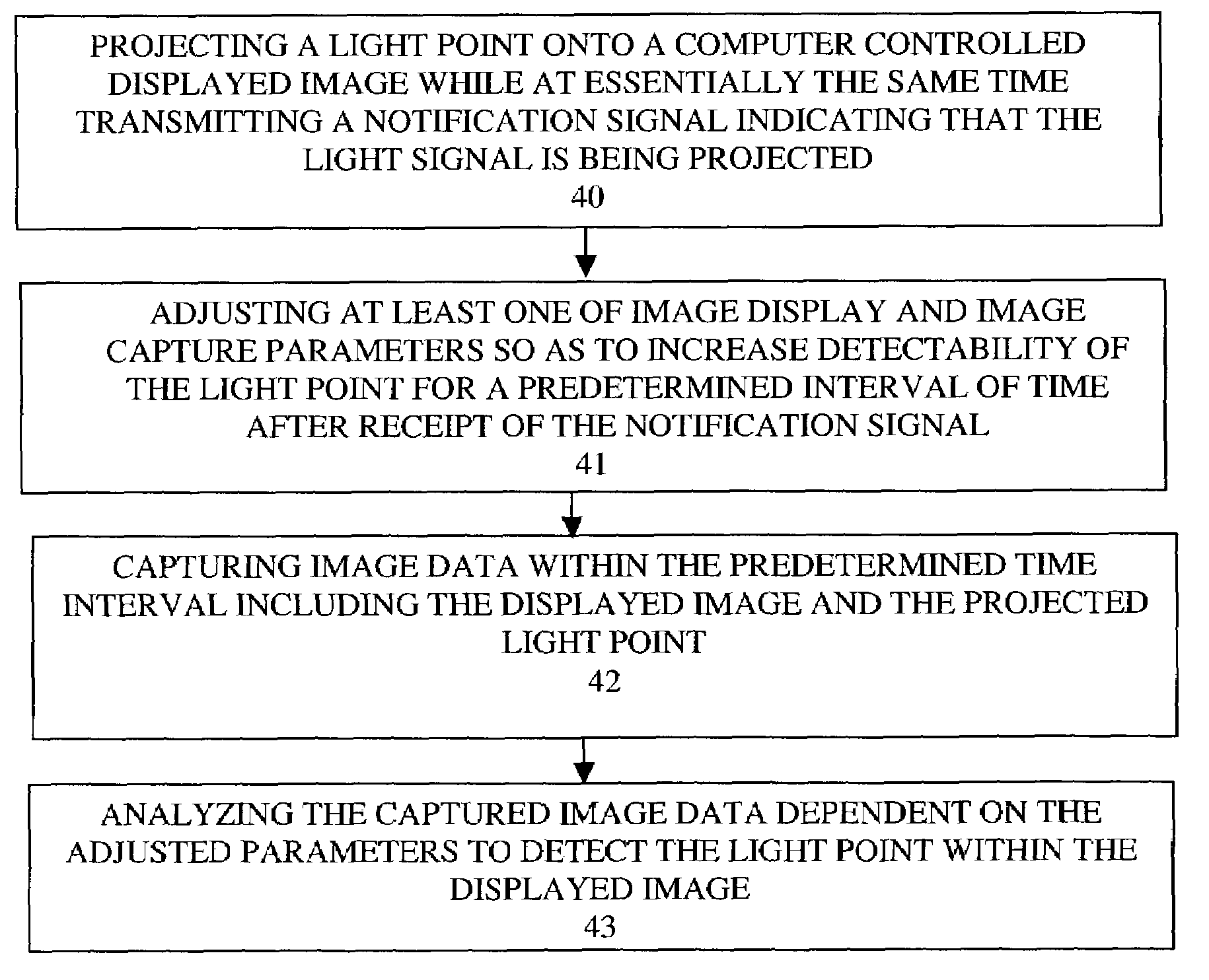
[0024]FIG. 4 shows the method of detecting a light point on computer controlled displayed images. Initially, a light point is projected on the displayed images at essentially the same time that a notification signal is transmitted indicating that the light signal is being projected (block 40). Next, at least one of image display or image capture parameters are adjusted to increase the detectability of the light signal for a predetermined time interval (block 41) after receipt of the notification signal. For instance, image capture parameters may be adjusted so as to cause a sensitivity to particular colors and intensities of the light point and / or to cause an insensitivity to all colors and intensities that are not the same as or similar to the light point. Alternatively, the display parameters can be adjusted such that the light point is more detectable within the adjusted displayed image (as will be described herein below).
[0025]The displayed image and the laser point are captured...
second embodiment
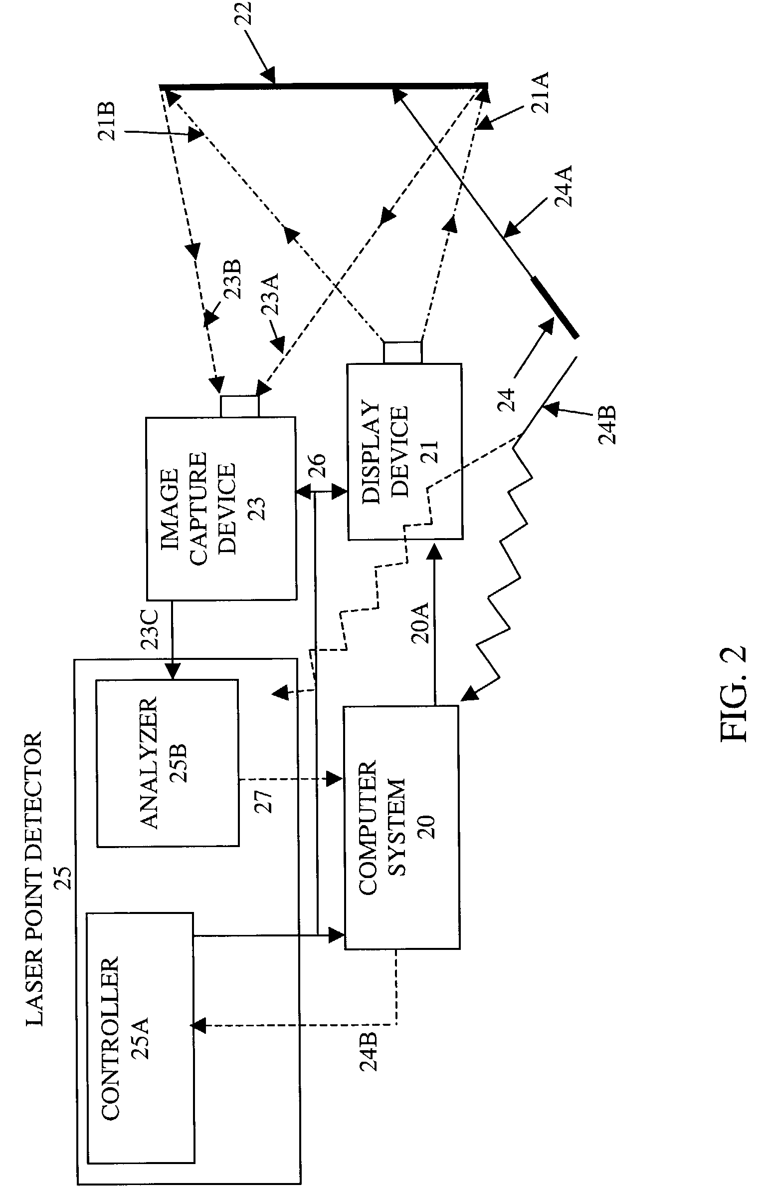
[0028]FIG. 5 shows the method of detecting a light point on a computer controlled displayed image. Similar to the method as shown in FIG. 4, a light signal is projected at a computer controlled displayed image while at essentially the same time a notification signal is transmitted indicating that the light signal is being projected (block 50). The displayed image intensity is reduced to at least a value that is less than a maximum value within a predetermined time interval after receipt of the notification signal (block 51). For example, referring to FIG. 2, the controller 25A can send control to the computer system 20 to cause image data 20A to be displayed such that any pixel value does not exceed the maximum value. In general, it should be understood that the intensity of pixel values has a dynamic range as defined by [0, c0]. For instance, an eight bit binary pixel value has a dynamic intensity range of 0-255. Hence, in one embodiment, the dynamic intensity range of the displaye...
PUM
 Abstract
Description
Claims
Application Information