Imaging system using markers

Active Publication Date: 2011-10-20
DEERFIELD IMAGING INC
View PDF4 Cites 46 Cited by
  • Summary
  • Abstract
  • Description
  • Claims
  • Application Information

AI Technical Summary

Benefits of technology

[0040]To aid the optical marker identification in different conditions, the patterns in the markers can be illuminated by active lighting (e.g. a light in behind the marker) and/or the markers can be enhanced to increase their likelihood of identification (e.g. phosphorescence). In addition, the optical marker patterns can be differentially enhanced within the marker pattern to further increase their detectability, and this can be applied differentially on separate markers that contain the same or different patterns.
[0041]To allow movement of one or more cameras, a tracking reference can be used. If the marker patterns are flat, then a tracking reference can contain a flat tracking pattern. However, since the object that the reference can be attached to for surgery (e.g. a head fixation device) can be placed in the surgical field at angles to optimize the effectiveness of the surgery independen

Problems solved by technology

These devices typically use infra-red or other non-visible optical tracking technology and suffer from a number of limitations including reduced capabilities with angulations of the tracked tool, difficulties in positioning a reference frame for tracking, inaccuracies from the positioning of the tracking reference as compared with the tracking field of view, and inaccuracies causes be contaminants (e.g., fingerprint on IR tracking sphere).
These common problems lead to poor utility and inaccuracies in tracking tools during surgery.
Relying on multiple markers can increase the system error (larger inaccuracy), increase the footprint/size of the tracked device and lead to poor ergonomic design of tracked devices.
The use of multiple generic markers in motion tracking applications (respiratory motion tracking) can place motion constraints on the tracking system that can lead to inaccuracies in motion tracking.
The standard markers that are available on the market today (IR spheres, X Points) do not have sufficient information associated with each marker to allow the use of a single marker

Method used


Image

  • Imaging system using markers
  • Imaging system using markers
  • Imaging system using markers

Examples


Example

[0067]In the drawing like characters of reference indicate corresponding parts in the figure.

DETAILED DESCRIPTION

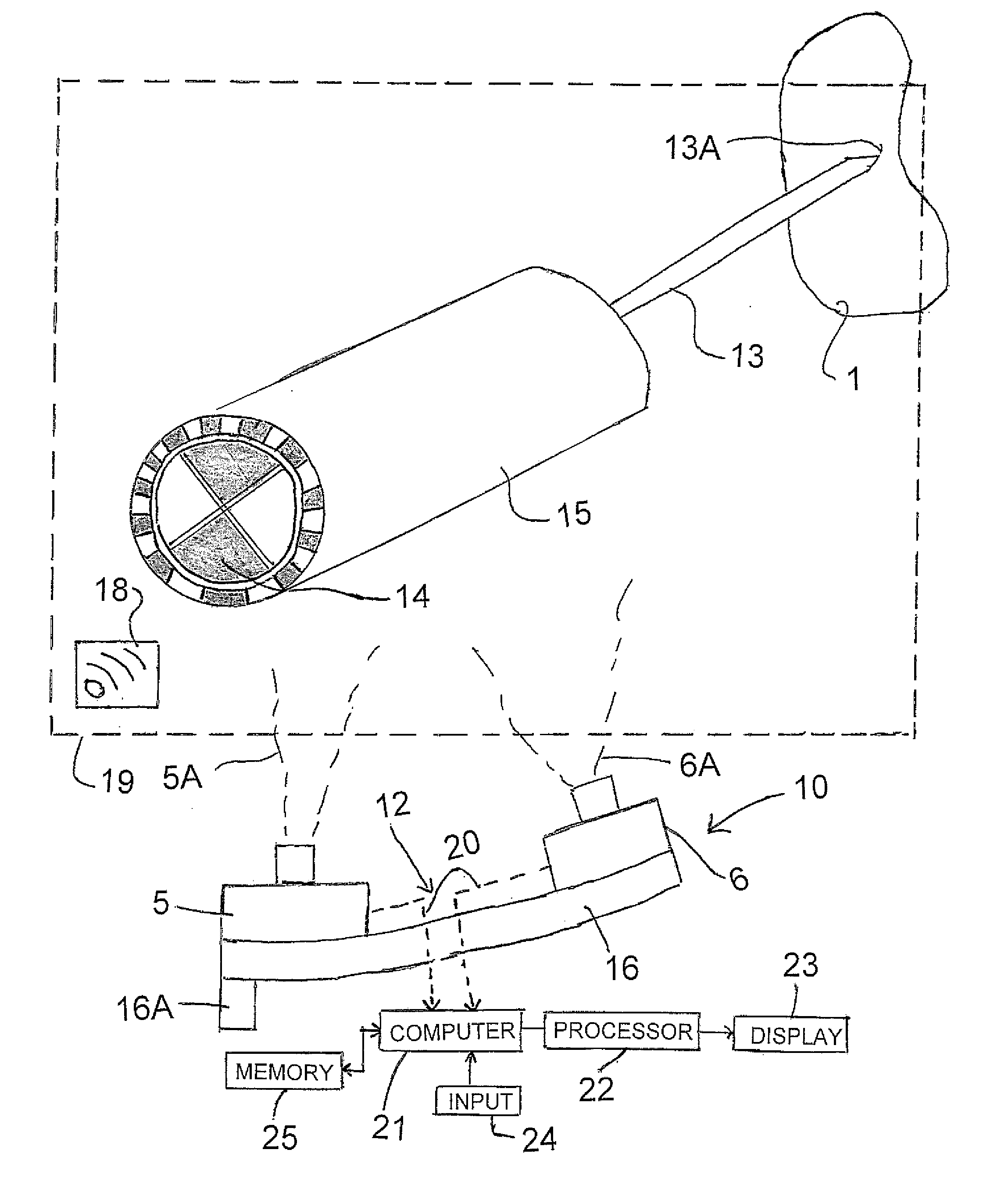
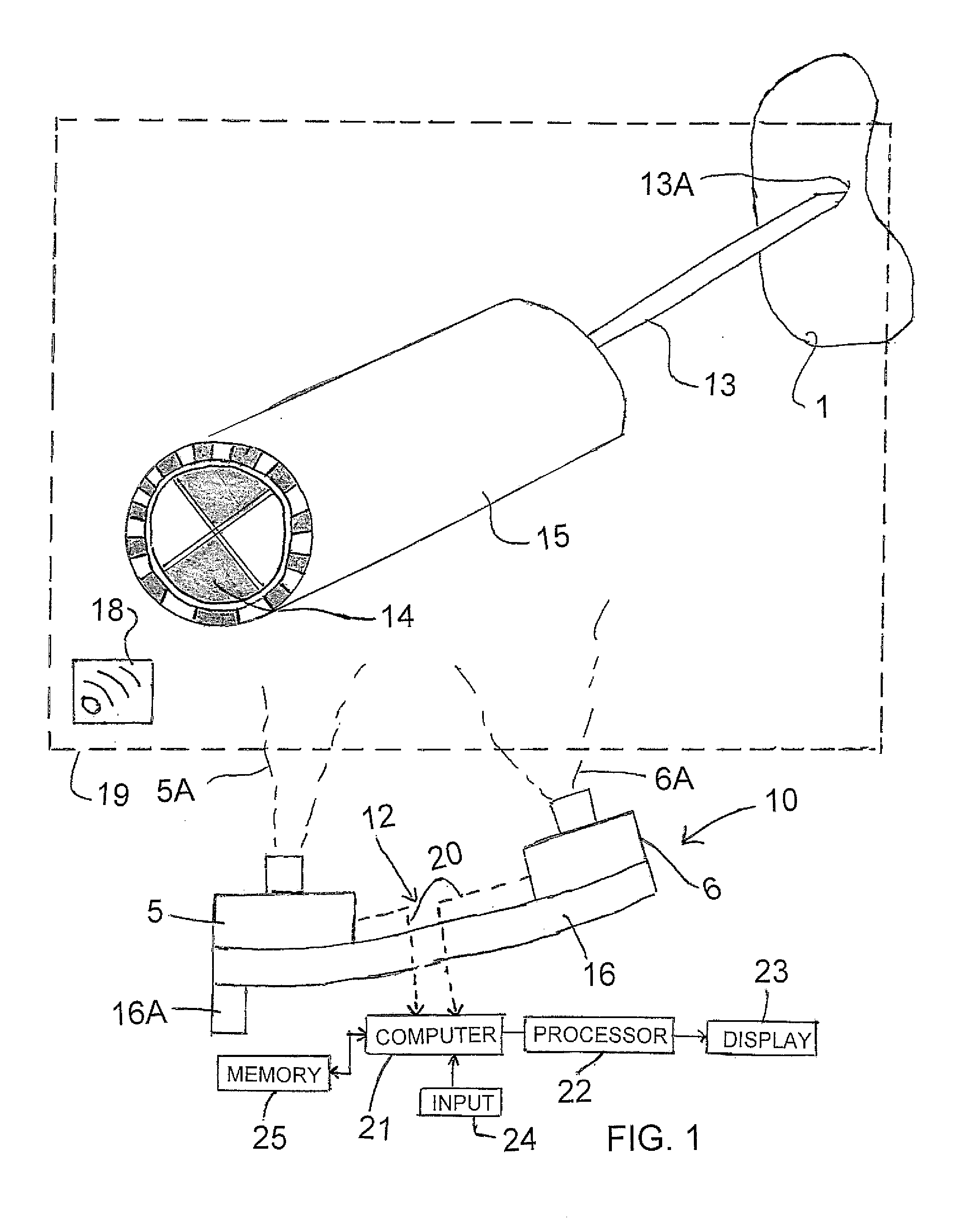
[0068]Referring to FIG. 1, a tracking system 10 has an optical sensor assembly 12 used to track the relative position and orientation of a marker 14 attached to an object 15, such as but not limited to a surgical tool 13 tracked in relation to a portion of a patient's anatomy 1 in a surgical scene or field of view 19. The sensor assembly 12 is a stereo sensor having a first digital video camera sensor with a first field of view 5A and a second digital video camera sensor 6 with a second partially overlapping field of view 6A. More than two cameras 5, 6 could also be used if desired. Suitable sensors or detector arrays for this purpose are commercially available. Such cameras are typically delivered pre-calibrated to allow the association of a pixel position in each of the images with a corresponding linear ray equation in a common sensor 3D space.

[0069]The position and or...


PUM


Abstract

A system for detecting a position of an object such as a surgical tool in an image guidance system includes a camera system with a detection array for detecting visible light a processor arranged to analyze the output from the array. Each object to be detected carries a single marker with a pattern of contrasted areas of light and dark intersecting at a specific single feature point thereon. The pattern includes components arranged in an array around the specific location arranged such that the processor is able to detect an angle of rotation of the pattern around the location and which are different from other markers of the system such that the processor is able to distinguish each marker from the other markers.

Description

[0001]This application claims the benefit of Priority under 35 USC 119 from Provisional Application 61 / 253,330 filed Oct. 20, 2009.[0002]This invention relates to an imaging system using markers with a camera responsive to visible light for detecting the markers. This system can be used for example for locating a position of an object in a field of view. The invention is particularly but not necessarily related to such detection systems for use in image guided surgery (IGS) where the object is a surgical tool.[0003]This application is related to copending U.S. application Ser. No. to be inserted filed to be inserted which claims priority from Provisional Application 61 / 255,735 filed Oct. 28, 2009, the disclosure of which is incorporated herein by reference.[0004]The image for the IGS can be obtained from any modality including MRI, CT, X-Ray, PET, Angio and Ultrasound.[0005]The imaging system can be used in surgical systems or in non-surgical systems.BACKGROUND OF THE INVENTION[0006...

Claims


Application Information

Patent Timeline
IPC IPC(8): H04N13/02
CPCA61B19/44A61B19/5244A61B2019/5483A61B2019/5255A61B2019/5265A61B2019/444A61B2090/3983A61B2034/2055A61B34/20A61B90/90A61B90/92A61B2034/2065A61B90/96A61B90/39
Inventor SCHAERER, SHAWNSCARTH, GORDONROBBINS, STEVEN
Owner DEERFIELD IMAGING INC
Why Eureka
Try Eureka