Enhanced ZScreen modulator techniques

a modulator and z-screen technology, applied in the field of z-screen, can solve the problems of z-screen designs when employed in the theatrical environment, double path length reducing the useful angle of view of the device, and analyzers in the eyewear selection device needing to be addressed

Active Publication Date: 2009-01-13
REAID INC
View PDF10 Cites 132 Cited by
  • Summary
  • Abstract
  • Description
  • Claims
  • Application Information

AI Technical Summary

Problems solved by technology

A double path length reduces the device's useful angle of view because the optical path length modulates the dynamic range or extinction characteristics of the sheet polarizer used with the device as a function of angle.
In addition to improvements to the ZScreen, issues with analyzers in the eyewear selection devices needed to be addressed.
Certain issues exist with an implementation such as that shown in FIG. 1A, particularly in the theatrical environment, where extremely high quality projection and viewing requirements exist.
Most notably, the previous ZScreen designs when employed in the theatrical environment suffer from inadequate image clarity, low dynamic range, slow transition time, poor transmission characteristics, and other performance issues.

Method used


Image

  • Enhanced ZScreen modulator techniques
  • Enhanced ZScreen modulator techniques
  • Enhanced ZScreen modulator techniques

Examples


Embodiment Construction

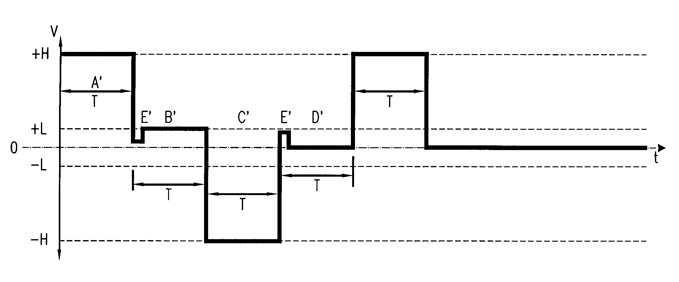
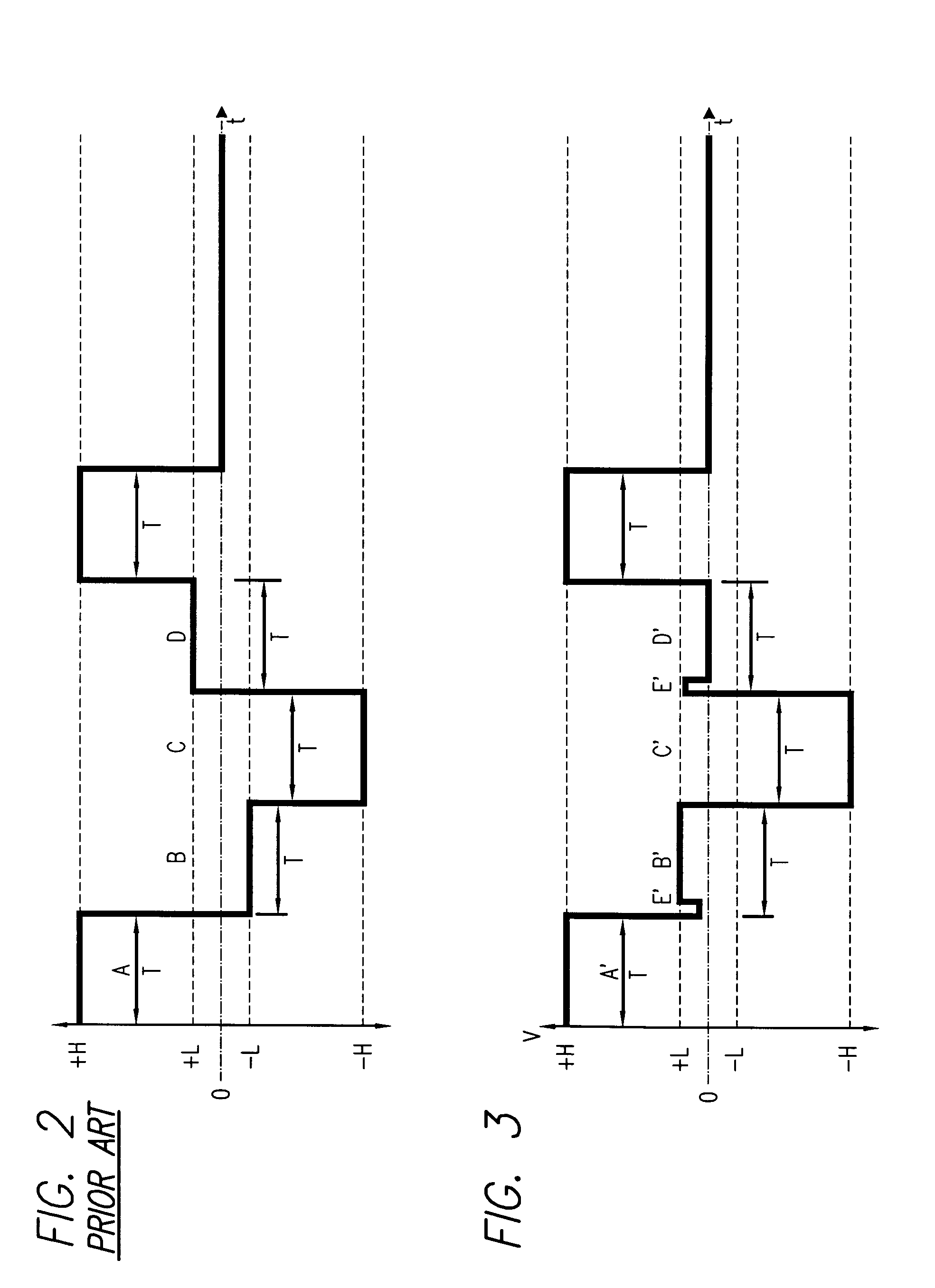
[0025]An enhanced ZScreen design comprising various improvements and enhancements, useful for theatrical projection, is provided. The improvements and methods used are described below. Taken together, the teachings disclosed combine to form an optically superior device and in deploying these changes a vast improvement can be obtained. This disclosure concentrates on those items that are unique, novel, and not obvious in their execution or application to workers versed in the art.

[0026]Operation of the ZScreen Device

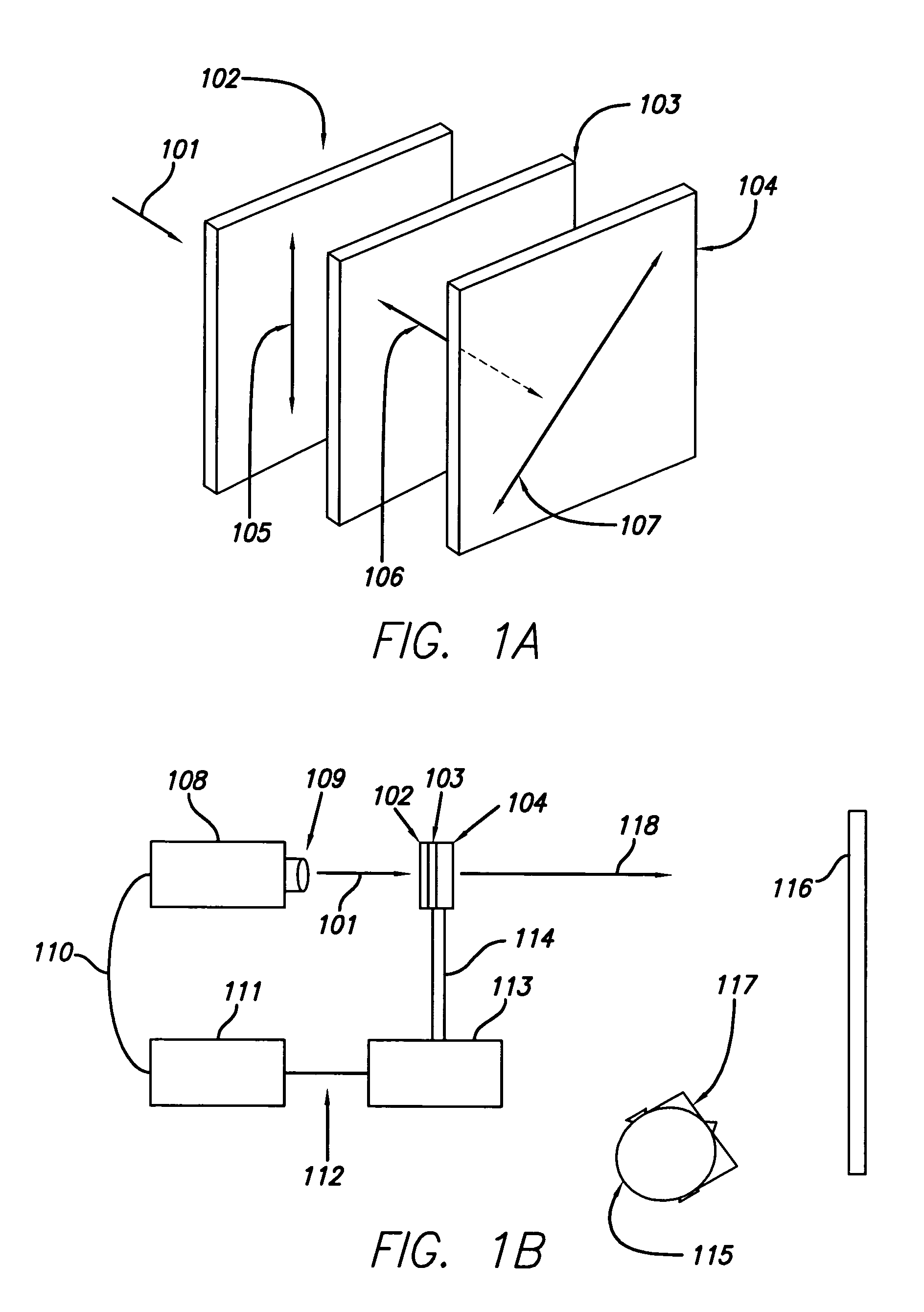
[0027]The ZScreen device of FIG. 1A shows linear sheet polarizer 102, an LC surface mode device or SMD 103, and another LC cell 104. With regard to FIG. 1A, in the case of polarized light, the behavior of the electric vector of the light waves is considered. The rays emerging from sheet polarizer 102 have their electric vector restricted to a plane that passes through axis 105. Such light is called linearly polarized light. The SMDs subsequently cause phase shifts to the ...


PUM


Abstract

A method and system for use in conjunction with a push-pull liquid crystal modulator system for creating circularly polarized light of alternating handedness is provided. The method and system comprise a pair of surface mode liquid crystal cells and a driver electrically coupled to the cells. The driver is configured to move an electrical charge using a quenching pulse comprising a relatively brief voltage spike at a beginning of a waveform period. Multiple additional improvements are provided, including reducing the thickness of the LC gap (the distance between cell electrode plates), creating a charge connection or wiring connection to the cell electrodes, employing anti-reflection coating technology, thinner ITO and ITO index matched to the LC material, bonding all possible air to material surfaces, using superior glass, employing more efficient polarizers, and reducing projector blanking time.

Description

[0001]This application claims the benefit of U.S. Provisional Patent Application 60 / 742,719, entitled “Quenching Pulse Speed Improvement for Push-Pull Modulator,” inventors Lenny Lipton and Matt Cowan, filed Dec. 6, 2005, which is incorporated herein by reference.BACKGROUND OF THE INVENTION[0002]1. Field of the Invention[0003]The present design relates generally to the art of stereoscopic polarizing modulators, and more particularly to improvements to the ZScreen®, a push-pull surface mode liquid crystal modulator having enhanced image clarity, dynamic range, transition time, transmission, and other characteristics.[0004]2. Background of the Invention[0005]The present device is an improved version of the push-pull liquid crystal (LC) modulator described by Lipton et al. in U.S. Pat. No. 4,792,850, issued on Dec. 20, 1988, the entirety of which is incorporated herein. Such a device, commonly called the ZScreen®, has been manufactured by StereoGraphics Corporation, originally as an on...

Claims


Application Information

Patent Timeline
Patent Type & Authority Patents(United States)
IPC IPC(8): G09G5/00G02B30/25H04N13/363
CPCG02F1/13471G03B21/56H04N13/0438H04N13/0459G02F1/0136G02F1/13306H04N13/341H04N13/363G03B21/00
Inventor COWAN, MATTGREER, JOSHLIPTON, LENNYCHIU, JOSEPH
Owner REAID INC
Why Eureka
Try Eureka