Electronic apparatus and thermal dissipating module thereof
a technology of electronic equipment and thermal dissipation module, which is applied in the direction of cooling/ventilation/heating modification, semiconductor/solid-state device details, semiconductor devices, etc., can solve the problems of destroying the capillary structure inconvenient and troublesome disassembly of the heat pipe, and light development of the electronic apparatus
- Summary
- Abstract
- Description
- Claims
- Application Information
AI Technical Summary
Benefits of technology
Problems solved by technology
Method used
Image
Examples
first embodiment
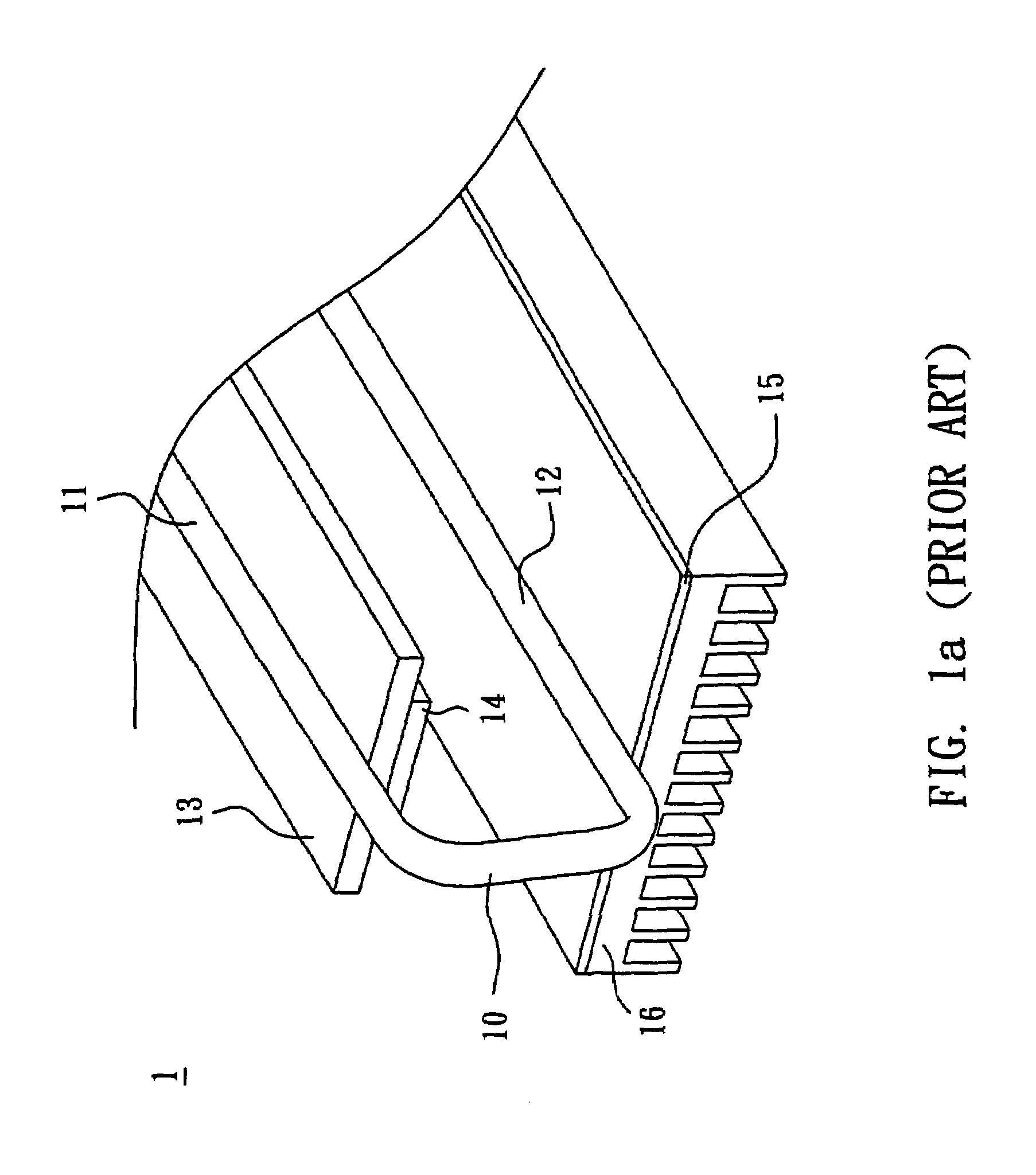
[0026]In FIGS. 2 and 3, a thermal dissipating module of the present invention is applied to an electronic apparatus 4. The electronic apparatus 4 has a thermal emitting device 41, a thermal dissipating device 42, and a thermal dissipating module 2. In this embodiment, the thermal emitting device 41 includes, but is not limited to, central processing unit (CPU) chips, graphic chips, display chips, or power supply. Besides, the thermal emitting device 41 has a thermal emitting surface 411, and the thermal dissipating device 42 may be a cast of the electronic apparatus 4 or a heat sink. The thermal dissipating device 42 has a thermal dissipating surface 421, and the thermal dissipating surface 421 has more than one thermal dissipating fins 422. Moreover, the thermal dissipating module 2 connects the thermal emitting device 41 and thermal dissipating device 42. The thermal dissipating module 2 comprises a heat pipe 21, a first joint component 22, and a second joint component 26.
[0027]Th...
second embodiment
[0037]As shown in FIG. 6, in accordance with the present invention, a thermal dissipating module 3 is disposed between a thermal emitting surface 411 and a thermal dissipating surface 421 in an electronic apparatus 4. The thermal dissipating module 3 has two heat pipes 31. Each of the two heat pipe 31 has two ends disposed respectively on the thermal emitting surface 411 and thermal dissipating surface 421. The two ends of each heat pipe 31 respectively connect a joint component 32. Similarly, the purposes for adjustment are reached by moving or rotating each heat pipe 31 to change the locations of each heat pipe 31 and its two ends.
[0038]In this embodiment, the two ends of each heat pipe 31 are disposed respectively on the same thermal emitting surface 411 and thermal dissipating surface 421. However, the first ends of the heat pipes 31 may be disposed on the same thermal emitting surface while the second ends of the heat pipes 31 may be disposed separately on two different thermal...
third embodiment
[0046]As shown in FIG. 8, in accordance with the present invention, a thermal dissipating module 6 has a heat pipe 61, a first joint component 62, and a second joint component 63. The first joint component 62 embraces one end of the heat pipe 61 and is disposed on a thermal emitting device 64. The first joint component 62 can also move in the thermal emitting device 64. The second joint component 63 embraces the other end of the heat pipe 61 and is fixed in the thermal dissipating device 65. In this embodiment, the second joint component 63 is fixed in the thermal dissipating device 65. However, to achieve the adjustable links for the thermal dissipating module 6, the angle of the heat pipe 61 can be changed by rotating one heat pipe's 61 end embraced by the second joint component 63. Besides, for the same purpose, the position of the heat pipe 61 can be changed by moving one heat pipe's 61 end embraced by in the first joint component 62.
[0047]In the first, second, and third embodim...
PUM
 Abstract
Description
Claims
Application Information
 - R&D
- Intellectual Property
- Life Sciences
- Materials
- Tech Scout
- Unparalleled Data Quality
- Higher Quality Content
- 60% Fewer Hallucinations
Browse by: Latest US Patents, China's latest patents, Technical Efficacy Thesaurus, Application Domain, Technology Topic, Popular Technical Reports.
© 2025 PatSnap. All rights reserved.Legal|Privacy policy|Modern Slavery Act Transparency Statement|Sitemap|About US| Contact US: help@patsnap.com


