Shelf connector

a technology for shelf connectors and connectors, which is applied in the direction of building scaffolds, coupling device connections, lighting support devices, etc., can solve the problems of inconvenient connection, troublesome disassembly and assembly procedures, and complicated assembling of the total structure, so as to facilitate disassembly and assembly, convenient disassembly and assembly, and easy assembly

Inactive Publication Date: 2009-01-20
LI XIANGMING
View PDF7 Cites 58 Cited by
  • Summary
  • Abstract
  • Description
  • Claims
  • Application Information

AI Technical Summary

Benefits of technology

[0008]In order to solve the above problems of existing arts, the object of the present invention is to provide a shelf connector. The shelf connector is suitable for connecting to various kinds of shelves having different specifications and purposes. Further, the shelf connector is very convenient to dissemble and assemble and the connection is reliable. Moreover, additional layers of shelves or other accessories can be easily assembled without detaching any part of the shelf structure. As a result, the use of the shelf is greatly enlarged.
[0009]In order to achieve the above objects, the shelf connector of the present invention comprises a sliding sleeve and a locking sleeve. The sliding sleeve is provided with a locking body thereon. The locking body is provided with an open groove along the axial direction of the sliding sleeve. The locking body is provided on both sides of the open groove with clasping portions. The locking sleeve is provided with a locking groove thereon. After the clasping portion is inserted into the locking groove, the width of the open groove can be reduced.
[0017]In the present invention, since the locking body of the sliding sleeve is provided with a through open groove thereon and the locking mechanism constituted of the locking sleeve and the sliding sleeve is utilized, the locking mechanism can reduce the width of the open groove to shrink inwardly after the locking sleeve is inserted into the clasping portion provided on the locking body of the sliding sleeve. Therefore, in assembling, the sliding sleeve can be conveniently positioned to any place of the supporting rod. Then, the insertion of the locking sleeve can fix it thereto. Further, since the locking sleeve has mounting portions for mating with the frame body of the shelf, or the locking sleeve itself is an end portion of the frame body of the shelf, the connection of the whole shelf becomes very simple. By using various connectors having different specifications and purposes, it is suitable for connecting various kinds of shelf. Meanwhile, in the present invention, other shelves can be additionally mounted on the shelf according to the conditions in use. Therefore, the functions and the field of application of the shelf can be extended.

Problems solved by technology

However, due to the different specifications of various kinds of shelves, it is inconvenient to connect with each other and the assembling of the total structure is very complicated.
With the above structure, although the height between two shelves can be adjusted according to the conditions in use, the disassembling and assembling procedures are very troublesome.
However, the above structure still has the drawbacks as follows: (1) Since the net bracket and the sleeve are integrally connected, the assembling of multiple layers of shelves is restricted.
That is, the shelves on both ends of the shelf pillar are easy to be dissembled whereas the shelves in the middle are not easy to assemble or dissemble; (2) Since the connection relies on the locking of conical surfaces, the supporting pillars and the shelf connectors are assembled more tightly due to the gravity after using a period of time.
Therefore, it is very difficult to detach the fixing sleeve from the fixing sleeve; (3) The manufacturing of the connector formed of the fixing sleeve and the clamping sleeve is more complicated, resulting in the rise of the manufacture cost of the shelf.

Method used


Image

  • Shelf connector
  • Shelf connector
  • Shelf connector

Examples


first embodiment

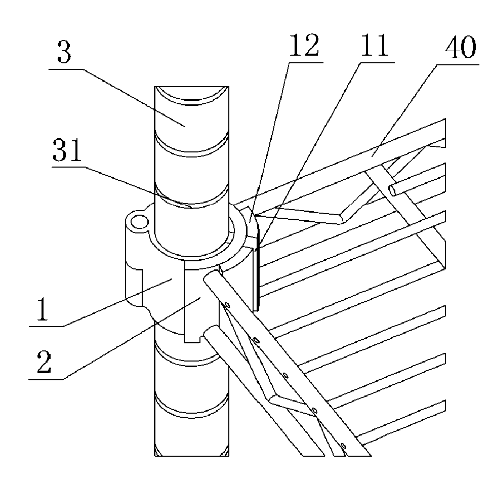
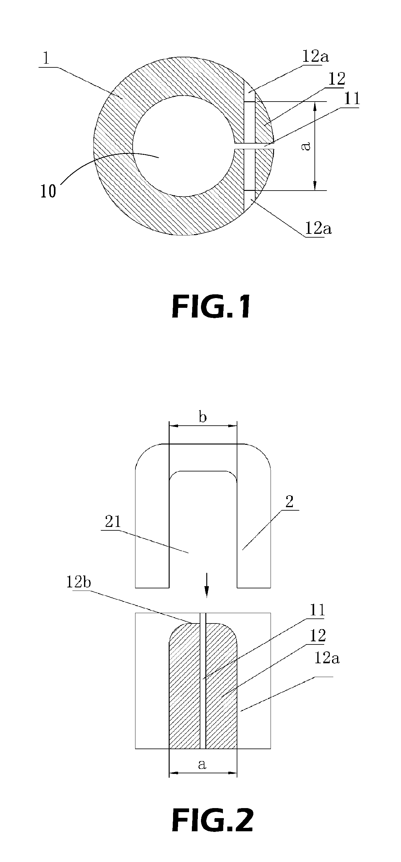
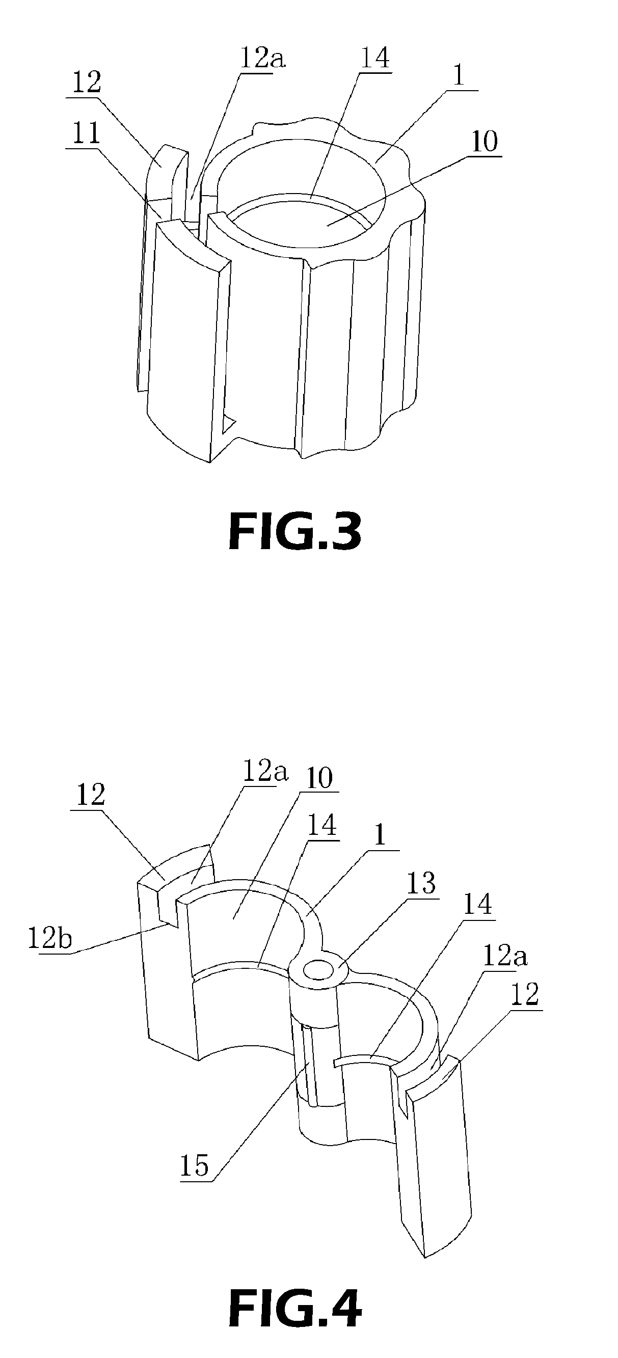
[0052]As shown in FIGS. 7 and 8, the present invention can be applied to a net-like shelf. The sliding sleeve 1 is a closed sleeve. The locking sleeve 2 is an arc plate. In this embodiment, the supporting rod 3 is connected with a horizontal net-like frame body 40 of the shelf. The procedure of the assembling of the shelf is as follows. After the sliding sleeve 1 is inserted into the suitable position of the supporting rod 3, the locking sleeve 2 in the corner of the frame body 40 of the shelf is inserted into the recessed clasping portion 12a of the sliding sleeve 1. With the inward shrinkage of the open groove 11, the supporting rod 3 can be fixedly connected to the frame body 40.

second embodiment

[0053]As shown in FIGS. 9 and 10, the present invention can be applied to a net-like shelf. The sliding sleeve 1 is an open sleeve. The locking sleeve 2 is also an arc plate. The procedure of the assembling of the shelf is as follows. The sliding sleeve 1 is radially inserted into the suitable position of the supporting rod 3 and the open sliding sleeve 1 is closed. Then, the locking sleeve 2 in the corner of the frame body 40 of the shelf is inserted from the top into the clasping portion 12a of the sliding sleeve 1. As a result, the supporting rod 3 can be fixedly connected to the frame body 40.

[0054]As shown in FIGS. 11 and 12, the third embodiment of the present invention can be applied to a plate-like shelf The sliding sleeve 1 can be a closed or open structure. The locking sleeve 2 is a horseshoe-shaped plate having a locking groove 21. The back of the locking sleeve 2 is fixedly connected with a sleeve seat 22 for combining with a connecting piece 24 having a “C-shaped” cross...

ninth embodiment

[0060]As shown in FIGS. 23 and 24, the present invention can be applied to a fixed article. The locking sleeve 2 comprises an arc portion 20 and sleeve seats 22 on both sides. The arc portion has a locking groove 21, and the sleeve seat 21 has a fixing hole 24. The locking sleeve 2 can be fixedly mounted to the wall or other fixed article by screws. The opening of the locking groove 21 is arranged upwardly. The frame body 44 of the shelf is provided on the sliding sleeve 1. In this way, by firstly connecting the sliding sleeve 1 and the locking sleeve 2 in the same manner as that in the previous embodiment, or by fixing the locking sleeve 2 onto the desired fixed article, then, the sliding sleeve 1 can be connected to the locking sleeve 2. As a result, the frame body 44 of the shelf can be mounted on any fixed article.

[0061]As shown in FIGS. 25 and 26, the tenth embodiment of the present invention can be applied to a disk-like shelf. The sliding sleeve 1 can be a closed or open stru...


PUM


Abstract

A shelf connector includes a sliding sleeve and a locking sleeve. The sliding sleeve is formed with a locking body thereon. The locking body is provided with an open groove along the axial direction of the sliding sleeve. The locking body is provided on both sides of the open groove with clasping portions. The locking sleeve is provided with a locking groove thereon. After the clasping portion is inserted into the locking groove, the width of the open groove can be reduced. With the above arrangement, in assembling, the sliding sleeve can be conveniently positioned to any suitable position of the supporting rod and locked thereto with the insertion of the locking sleeve. Since the locking sleeve itself has mounting portions for mating with the frame body of the shelf, or the locking sleeve itself is the end portion of the frame body of the shelf, the connection of the whole shelf becomes very simple. By using various connectors having different specifications and purposes, it is suitable for connecting various kinds of shelf.

Description

BACKGROUND OF THE INVENTION[0001]1. Field of the Invention[0002]The present invention relates to a shelf connector, and in particular to a shelf connector capable of mounting on a shelf.[0003]2. Description of Prior Art[0004]In daily life, a shelf constituted of brackets, hangers or supports has been widely used. However, due to the different specifications of various kinds of shelves, it is inconvenient to connect with each other and the assembling of the total structure is very complicated. In view of the above problems, China Patent Publication No. CN2503777Y discloses a shelf connector comprising a supporting rod, a connector and a net bracket. The supporting rod is axially provided with several positioning grooves at identical intervals. The connector is formed of two arc pieces. Both sides of the two arc pieces are provided with male and female engaging members, respectively, so as to form a cone after engaging with each other. The cone has a mouth portion tapering from bottom...

Claims


Application Information

Patent Timeline
Patent Type & Authority Patents(United States)
IPC IPC(8): E04G7/18
CPCA47B57/545A47B57/562F16B7/048Y10T403/7182Y10T403/7111
Inventor LI, XIANGMING
Owner LI XIANGMING
Why Eureka
Try Eureka