Rotatable chuck

a chuck and chuck technology, applied in the field of chucks, can solve the problems of time-consuming use of chucks, requiring numerous work tool changes, and the time required to finish a job may be longer than desired

Inactive Publication Date: 2009-01-20
EASTWAY FAIR
View PDF47 Cites 45 Cited by
  • Summary
  • Abstract
  • Description
  • Claims
  • Application Information

AI Technical Summary

Problems solved by technology

This may make the use of a chuck time-consuming, since tightening and loosening often involves rotating the adjustment ring numerous times until the jaws are sufficiently tight against the work tool shaft or sufficiently loose to allow the work tool to be removed from the chuck.
This may be a particular disadvantage in operations where a user is likely to use several different work tools during a job and may need to change work tools repeatedly.
For example, this may be a problem in drilling and screwing jobs where a user needs to drill a number of pilot holes and then drive screws into the pilot holes.
This may require numerous work tool changes between drill bits and driver bits during the course of the job.
Because many conventional chucks must be manually operated, the time required to finish a job may be longer than desired and the user may tire before the job is done.
Another problem with manually operated chucks is that the user may sometimes fail to fully tighten the chuck.
This may cause the jaws to lose their grip on the work tool when the power tool is operated.
Usually, this results in the power tool and the chuck spinning around the shaft of the work tool without transferring rotational torque.
This can be particularly annoying and inconvenient to a user, especially in the middle of a long job where the user has had to manually change a work tool numerous times. Sometimes a user may also have difficulty loosening a chuck to remove work tools.
This may occur when the user overtightens the chuck or may occur due to unintentional tightening during use.
This can also be frustrating and may increase the amount of time needed to finish a project.

Method used


Image

  • Rotatable chuck
  • Rotatable chuck
  • Rotatable chuck

Examples


Embodiment Construction

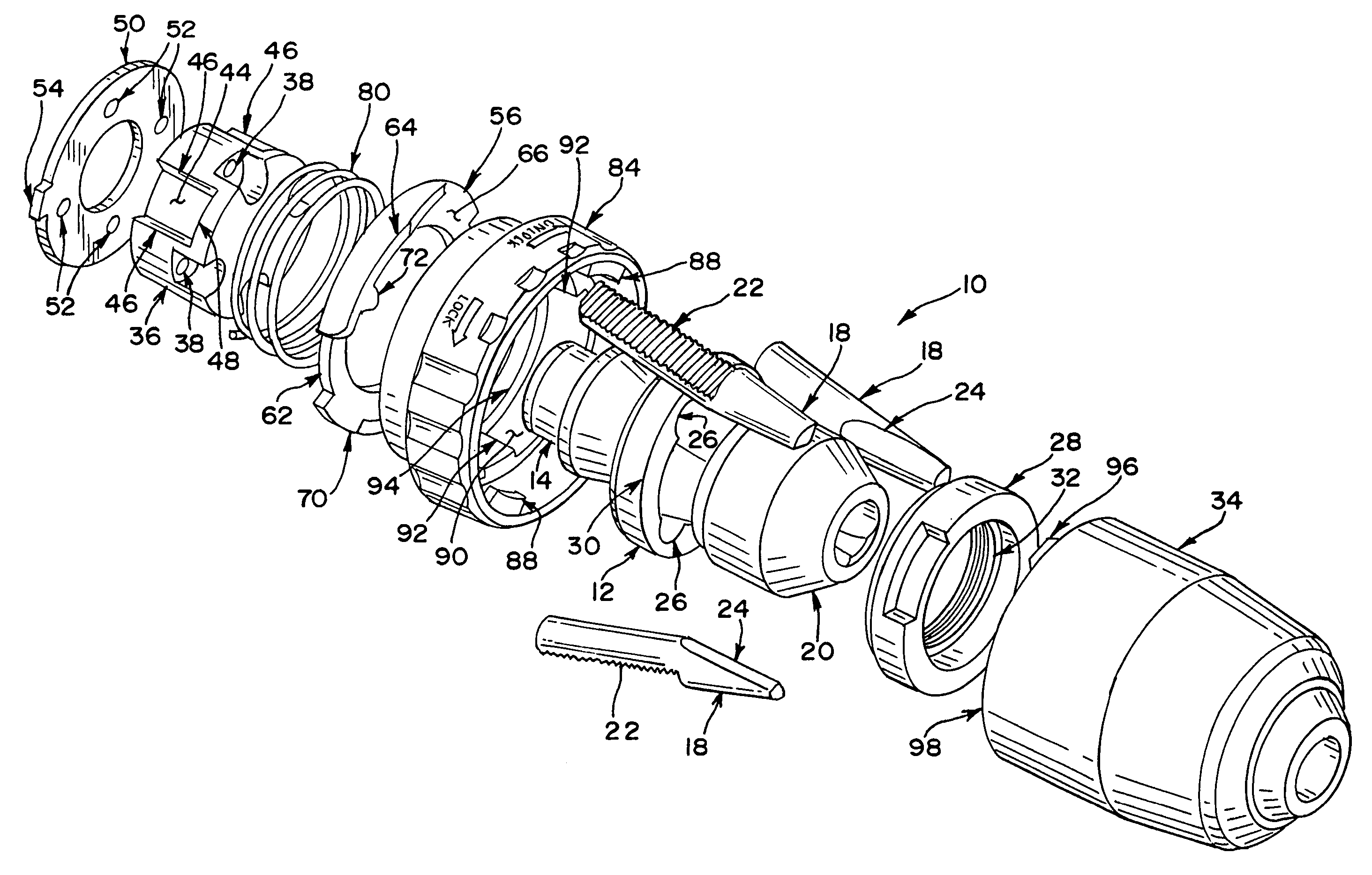
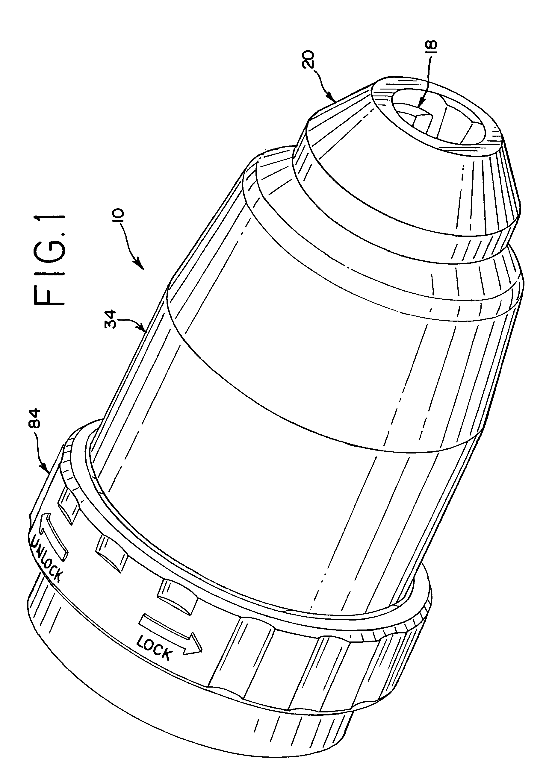
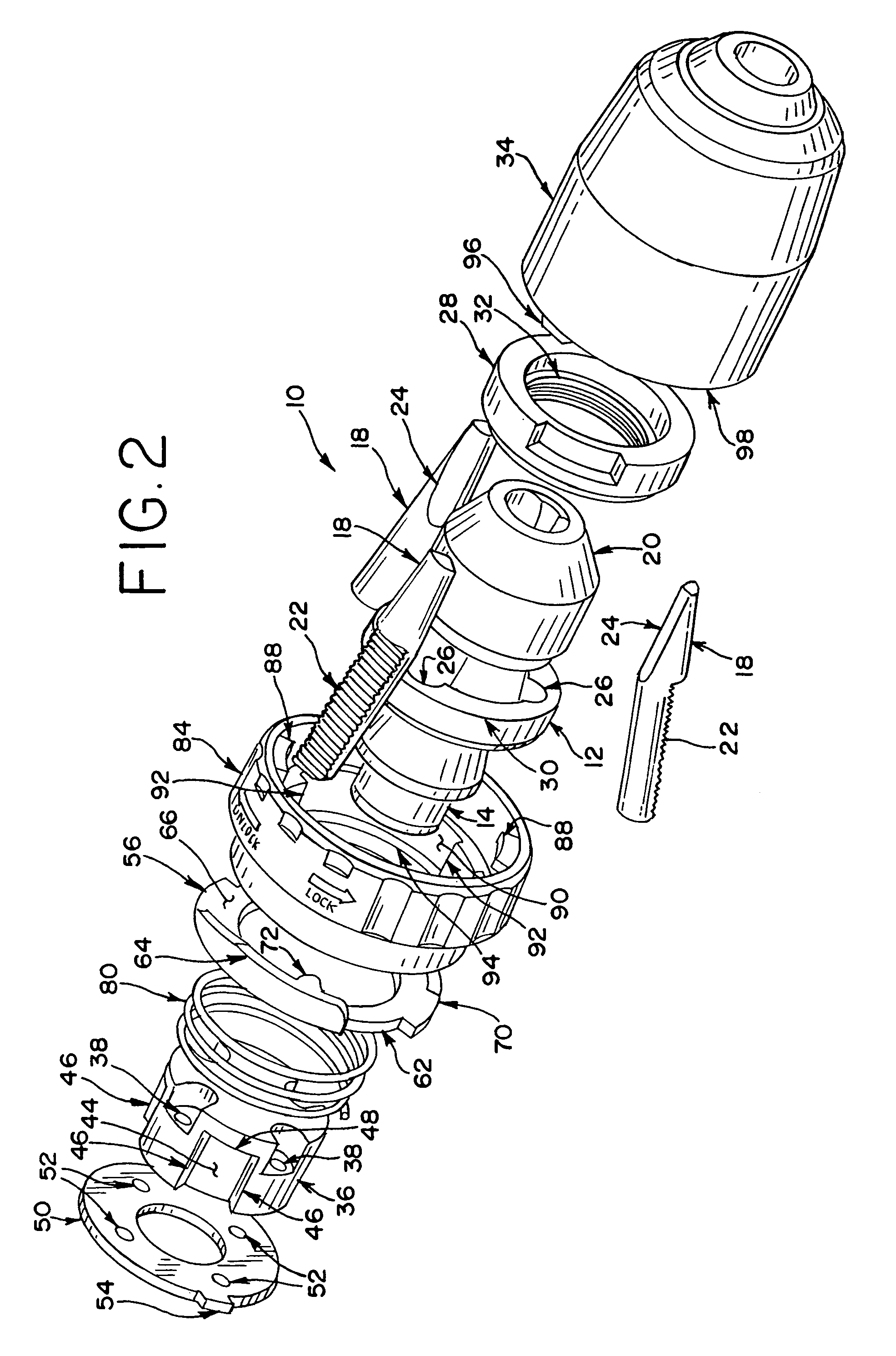
[0043]Referring now to the drawings, and particularly to FIGS. 1 through 12, one embodiment of an auto-lock chuck 10 is shown. As shown in FIG. 4, the auto-lock chuck 10 includes a body 12 that may be threadably attached at the rear end 14 thereof to the drive shaft 16 of a power tool. Thus, the body 12 is rotatable in response to rotation of the drive shaft 16. The auto-lock chuck 10 also includes a series of three jaws 18 at the forward end 20 thereof that are capable of gripping the shaft of a work tool. As shown in FIG. 2, each of the jaws 18 have threads 22 on the outside surfaces at the rear ends thereof and include jaw faces 24 on the inside surfaces at the front ends thereof. The jaws 18 are mounted within bores 26 angularly positioned through the body 12 and spaced equally thereabout. An adjustment ring 28 is mounted within a groove 30 in the body 12 and is longitudinally restrained by the groove 30. The adjustment ring 28 includes threads 32 on the inner diameter which are...


PUM

PropertyMeasurementUnit
forceaaaaaaaaaa
rotationaaaaaaaaaa
tightening torqueaaaaaaaaaa

Abstract

A chuck is provided with a body, a plurality of jaws and an adjustment ring. The adjustment ring is threadably engaged with the jaws. When the adjustment ring is rotated in one direction, the jaws tighten by moving closer to each other. When the adjustment ring is rotated in the opposite direction, the jaws loosen by moving away from each other. An impact member is also provided for engagement with the adjustment ring. When the drive shaft of the power tool is rotated, the adjustment ring impacts against the impact member. As a result, the adjustment ring and the body of the chuck rotate relative to each other causing the jaws of the chuck to loosen or tighten depending on the direction the drive shaft is rotating.

Description

BACKGROUND[0001]The present invention relates generally to chucks and more particularly to a chuck that may be locked or unlocked by rotating the drive shaft of a power tool.[0002]Chucks are well known and are used in many applications. In general, a chuck is connected to the drive shaft of a power tool. One common example of the type of power tool that a chuck may be used on is an electric drill. However, chucks are also used on numerous other tools, such as screw drivers, nut drivers and grinders. Moreover, power tools may be powered by pneumatics, electricity, manual power or by other power sources. Chucks are generally used to grip the shaft of various work tools so that the work tool rotates with the drive shaft of the power tool. Typical types of work tools that may be used with a chuck include drill bits, screwdriver bits and grinding disks or stones.[0003]A wide variety of chucks have been developed. The most common type of chuck that is employed uses three jaws to grip the ...

Claims


Application Information

Patent Timeline
Patent Type & Authority Patents(United States)
IPC IPC(8): B23B31/163
CPCB23B31/123B23B31/1238B23B45/02B23B2231/06Y10T279/17632Y10T279/32Y10T408/953Y10T279/27B23B2231/38
Inventor ZHOU, JIN LINZHAO, XIAN GUOLAM, CHIN HUNGCUI, ZHI QINCHUNG, KOON FOR
Owner EASTWAY FAIR
Why Eureka
Try Eureka