Micro-fluidic oscillator having a sudden expansion region at the nozzle outlet

a microfluidic oscillator and expansion region technology, applied in the direction of liquid/fluent solid measurement, instruments, transportation and packaging, etc., can solve the problem that fluid can still generate oscillations at very slow flow speeds, and achieve the effect of increasing the viscosity of fluid

Inactive Publication Date: 2009-01-27
NATIONAL TSING HUA UNIVERSITY
View PDF6 Cites 23 Cited by
  • Summary
  • Abstract
  • Description
  • Claims
  • Application Information

AI Technical Summary

Problems solved by technology

Therefore, fluid can still generate oscillation under very slow flow speeds.

Method used


Image

  • Micro-fluidic oscillator having a sudden expansion region at the nozzle outlet
  • Micro-fluidic oscillator having a sudden expansion region at the nozzle outlet
  • Micro-fluidic oscillator having a sudden expansion region at the nozzle outlet

Examples


Embodiment Construction

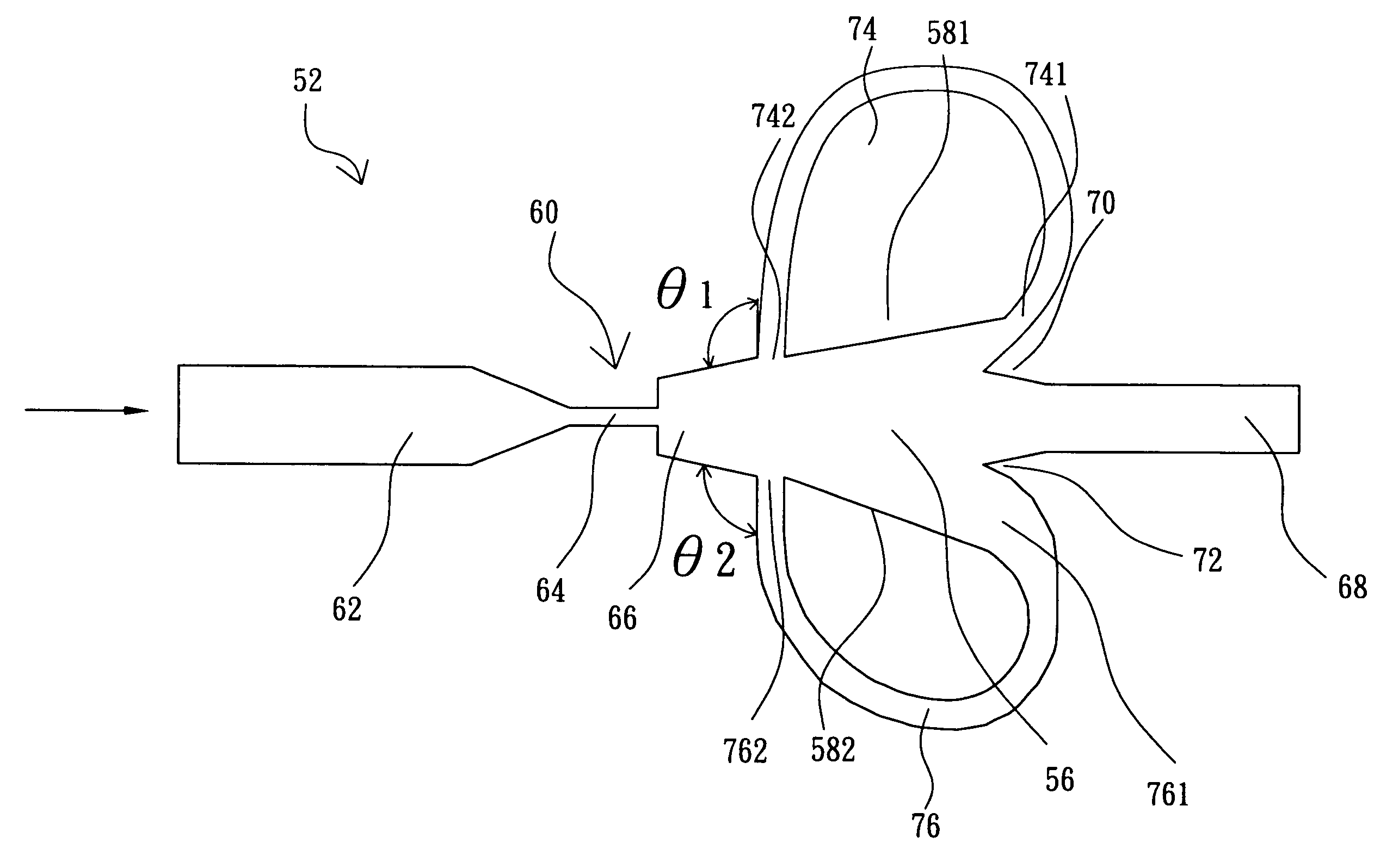
[0022]As shown in FIGS. 4 and 5, a micro fluidic oscillator 50 of the present invention comprises a main body 52 and a cover body 54 for covering the main body 52. The main body 52 comprises an oscillation chamber 56 with two sides formed of two attachment walls 581 and 582, a sudden-expansion micro nozzle 60, an outlet passage 68, two flow splitters 70 and 72, and two feedback channels 74 and 76. The oscillation chamber 56 is used to provide an oscillation space for a fluid. The sudden-expansion micro nozzle 60 has an inlet passage 62, a jet stream passage 64 and a sudden-expansion region 66. One end of the sudden-expansion region 66 is connected with the jet stream passage 64, and the other end of the sudden-expansion region 66 is connected with one end of the oscillation chamber 56. The outlet passage 68 is connected with the other end of the oscillation chamber 56. The two flow splitters 70 and 72 are located at the connection positions of the outlet passage 68 and the oscillati...


PUM


Abstract

A micro-fluidic oscillator comprises a main body and a cover body for covering the main body. An oscillation chamber is disposed on the main body to provide an oscillation space for fluid. A sudden-expansion micro-nozzle is connected with one end of the oscillation chamber, and an outlet passage is connected with the other end of the oscillation chamber. Two fluid-separating bodies are located at the connection positions of the outlet passage and the oscillation chamber, respectively. Two feedback channels are located outside two attachment walls. The sudden-expansion micro-nozzle is used to break the viscous shear stress between fluid and the walls and to generate unstable flow and oscillation. Moreover, the two feedback channels have different lengths, inside diameters and alternate outlet positions to further enhance the oscillation of fluid.

Description

BACKGROUND OF THE INVENTION[0001]1. Field of the Invention[0002]The present invention relates to a micro-fluidic oscillator and, more particularly, to a micro-fluidic oscillator having a sudden-expansion micro nozzle to conquer fluid viscous force due to increase of instability of fluid so as to generate a self oscillation phenomenon at slow flow.[0003]2. Description of Related Art[0004]A fluidic oscillator makes use of instability of the fluid itself to generate oscillation. Because of restrictions of physical parameters, general fluidic oscillators can only generate oscillation under some flow speeds. If the flow speed is too low, the fluidic oscillators cannot successfully generate oscillation. This will result in much limit in applications, especially in the applications of micro fluidic.[0005]As shown in FIG. 1, U.S. Pat. No. 3,902,367 discloses a fluidic oscillator 2 , which comprises an oscillation chamber 4 with attachment walls 61 and 62 at two sides thereof, a fluid inlet ...

Claims


Application Information

Patent Timeline
Patent Type & Authority Patents(United States)
IPC IPC(8): G01F1/20
CPCF15C1/22Y10T137/2229Y10T137/2224
Inventor YANG, JUNG-TANGCHEN, CHI-KOTSAI, KUN-CHIH
Owner NATIONAL TSING HUA UNIVERSITY
Why Eureka
Try Eureka