Smoke exhauster

A range hood and fan technology, which is applied in the field of kitchen appliances, can solve problems such as complex structure, low feasibility, and difficulty in integrating range hoods, and achieve the effect of improving smoking capacity

Inactive Publication Date: 2017-02-15
NINGBO FOTILE KITCHEN WARE CO LTD
View PDF13 Cites 1 Cited by
  • Summary
  • Abstract
  • Description
  • Claims
  • Application Information

AI Technical Summary

Problems solved by technology

However, this range hood has a complicated structure, and it is difficult to integrate with the existing range hood, so the feasibility of applying it to actual products is not high.

Method used


Image

  • Smoke exhauster
  • Smoke exhauster
  • Smoke exhauster

Examples


Embodiment 1

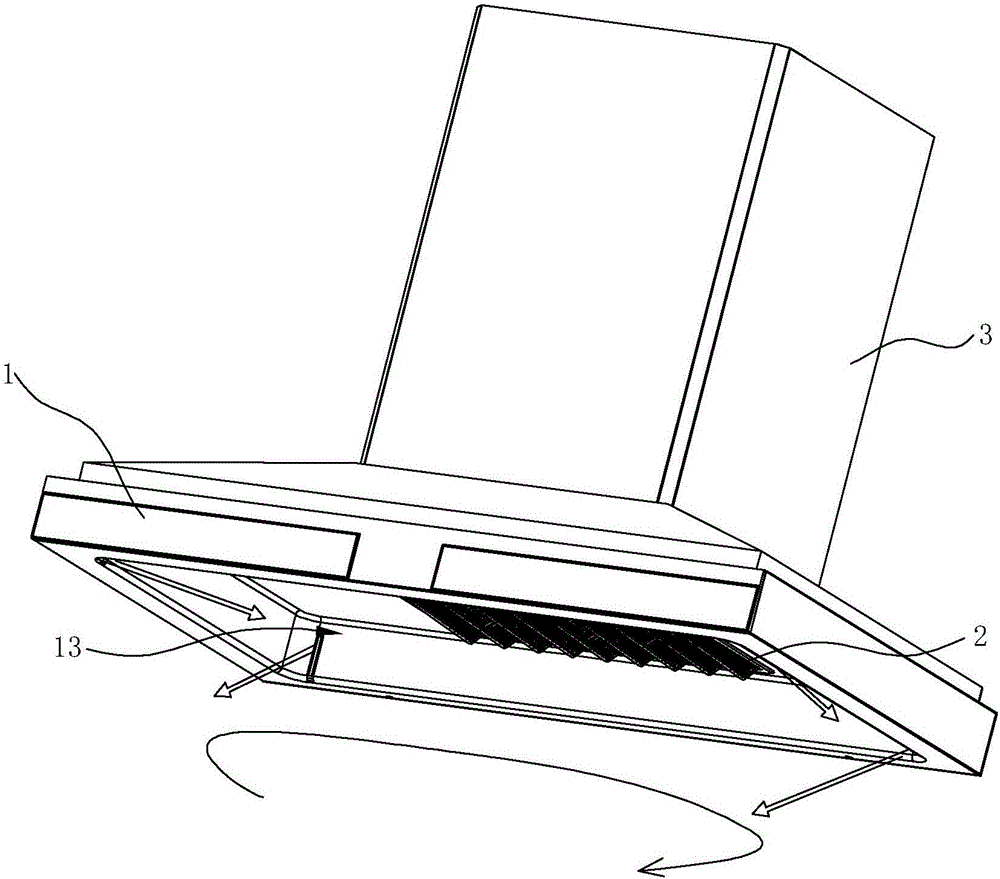
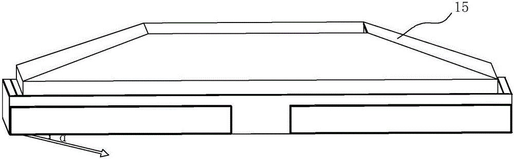
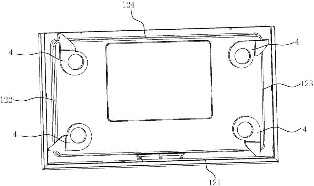
[0039] see Figure 2 ~ Figure 6 The smoke collecting hood 1 includes a top surface 11 and side surfaces, and the side surfaces include a front side 121, a left side 122, a right side 123 and a rear side 124. The smoke collecting hood 1 formed by the above five surfaces is concave to form a smoke collecting cavity 13. The bottoms of the above four sides extend outward to form a bottom surface, which corresponds to the side surfaces, including a front bottom surface 141, a left bottom surface 142, a right bottom surface 143 and a rear bottom surface 144. The bottom surface is turned upward at the outer edge, and a top plate is arranged above the fold 15. The top plate 15 is used to connect with the chassis 3.

[0040] In this embodiment, the air curtain device 4 is arranged at four corners on the top surface 11 . The air curtain device 4 includes a fan 41 and an air outlet device 42 , and the air outlet device 42 is formed with an air inlet 421 and an air outlet 422 . The blo...

Embodiment 2

[0044] see Figure 7 ~ Figure 9 , the difference from the first embodiment above is that in this embodiment, the air curtain device 4' includes a fan 41, an air outlet device 42, an air duct 43 and a drainage pipe 44, and an air inlet 421 is formed on the air outlet device 42 Along with the air outlet 422 , the air duct 43 is also formed with an air duct air inlet 431 and an air duct air outlet 432 . Fan 41 is connected with the air duct air inlet 431 of air duct 43, and the air duct air outlet 432 of air duct 43 is connected with one end of drainage pipe 44, and the other end of drainage pipe 44 is connected with the air inlet 421 of air outlet device 42, and drainage Tube 44 is preferably a rubber hose. The air outlet 422 of the air outlet device 42 is formed in a strip shape extending in the longitudinal direction, and each side of the smoke collecting hood 1 is provided with an air outlet hole 16 extending in the longitudinal direction at a position corresponding to the a...

Embodiment 3

[0047] see Figure 10 ~ Figure 12 , in this embodiment, only two air curtain devices 4 "are needed. Compared with the air curtain device 4' in Embodiment 2, the air curtain device 4 " is different in that the air outlet of the air curtain device 4 " There are two sets of devices 42 , air ducts 43 and drainage pipes 44 , and the two air ducts 43 are respectively connected to the two air outlets of the fan 41 , thereby forming a form of double-outlet fan rubber hose connection.


PUM


Abstract

The invention discloses a smoke exhauster. The smoke exhauster comprises a smoke collecting hood; the smoke collecting hood is provided with air curtain devices; each air curtain device comprises a draught fan and an air outlet device communicating with the draught fan; and each air outlet device is provided with an air outlet. The smoke exhauster is characterized in that each side of the smoke collecting hood is provided with an air outlet hole, the air outlet holes in every two adjacent sides are far away from each other, and the air outlets correspond to the air outlet holes; and an included angle between induced rotational flow blown by each air curtain device through the corresponding air outlet hole and the horizontal direction is formed, and divided flow, in the horizontal direction, of the induced rotational flow forms same-direction rotational flow. Shear force in the horizontal direction is provided through the blown induced rotational flow, rotary motion is transferred through the viscous shear force and turbulent shear force of fluid, airflow directions do not interfere with each other, and the same-direction rotational flow is formed; thus, smoke outleakage is effectively shielded, meanwhile, the induced draft negative pressure is decreased, and a smoke suction area of the smoke exhauster is controlled; and moreover, cyclone sucking is formed, so that a negative pressure area of the smoke exhauster extends downwards, and the smoke collecting and sucking capacity is improved.

Description

technical field [0001] The invention relates to a kitchen appliance, in particular to a range hood. Background technique [0002] The traditional range hood can be regarded as a point-sink type of suction, the energy of the suction airflow decays quickly, and as the distance from the sink increases, the flow velocity decays quadratically, resulting in a very small smoking area actually controlled by the range hood. Small. At present, some range hoods achieve a better range hood effect by increasing the air volume, which results in sucking a large amount of air in order to discharge a little range hood, that is, the actual range hood efficiency of range hood is not high. [0003] In order to solve the above-mentioned shortcomings, a range hood that forms an air curtain to prevent the oil fume from overflowing has been proposed, such as a hidden air curtain range hood disclosed in Chinese patent application No. 201110327839.2, which includes an outer cover, a smoke collection...

Claims


Application Information

Patent Timeline
Patent Type & Authority Applications(China)
IPC IPC(8): F24C15/20
CPCF24C15/2028
Inventor 李志峰陈浩辉茅忠群诸永定李斌
Owner NINGBO FOTILE KITCHEN WARE CO LTD
Why Eureka
Try Eureka