Extractor hood

A range hood and fan technology, which is applied in the field of kitchen appliances, can solve problems such as complex structure, low feasibility, and difficulty in integrating range hoods, and achieve the effect of improving smoking capacity

Active Publication Date: 2017-03-22
NINGBO FOTILE KITCHEN WARE CO LTD
View PDF12 Cites 1 Cited by
  • Summary
  • Abstract
  • Description
  • Claims
  • Application Information

AI Technical Summary

Problems solved by technology

However, this range hood has a complicated structure, and it is difficult to integrate with the existing range hood, so the feasibility of applying it to actual products is not high.

Method used


Image

  • Extractor hood
  • Extractor hood
  • Extractor hood

Examples


Embodiment 1

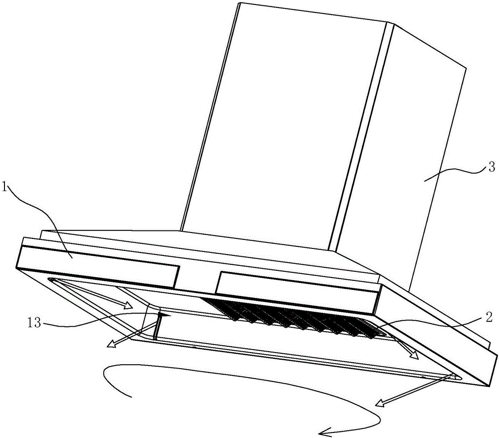
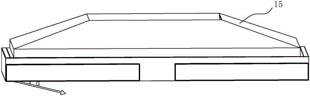
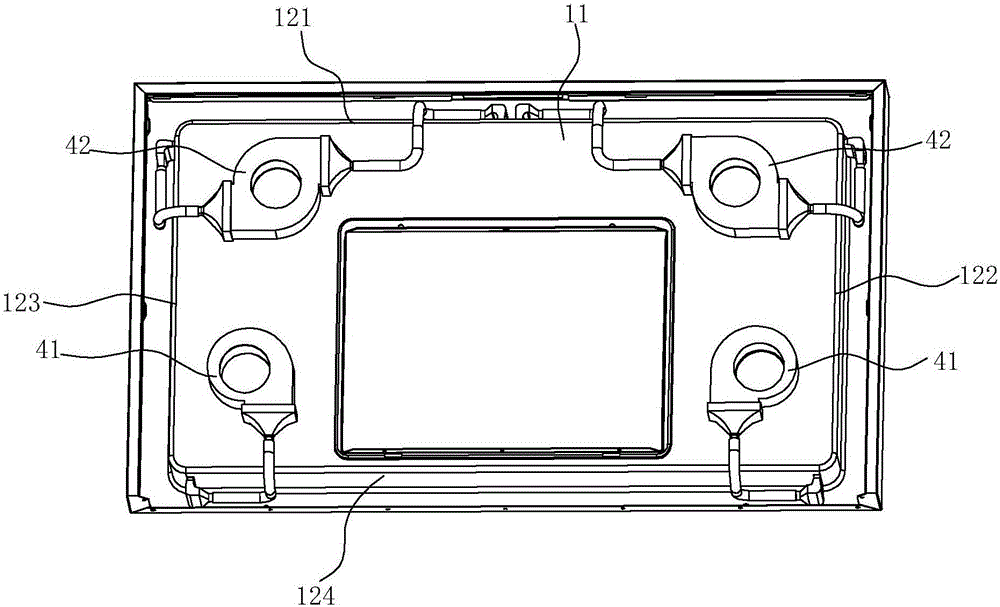
[0041] see Figure 2 ~ Figure 4 The smoke collecting hood 1 includes a top wall 11 and side walls, and the side walls include a front side wall 121 , a left side wall 122 , a right side wall 123 and a rear side wall 124 , and the above five walls together form a concave smoke collecting chamber 13 . The outer circumference of the bottom of the above four side walls extends outwards to form a bottom surface. The bottom surface and the side walls correspond to each other, including a front bottom surface 141, a left bottom surface 142, a right bottom surface 143 and a rear bottom surface 144. A top plate 15 is arranged above, and the top plate 15 is used for connecting with the chassis 3 .

[0042] The air curtain device comprises two first air curtain devices 41 and two second air curtain devices 42, the first air curtain devices 41 are located at two corners of the top wall 11 rear side respectively, and the second air curtain devices 42 are respectively located at the top Th...

Embodiment 2

[0049] see Image 6 , in this embodiment, the difference from the first embodiment above is that the angle α between the induced swirl flow and the horizontal direction or by setting a plurality of parallel arrangements in the first air outlet device 44 and the second air outlet device 44' achieved with longitudinally inclined partitions 442, Image 6 Take the second air outlet device 44' as an example. At this time, an air outlet hole 16 is formed on each bottom surface of the outer periphery of the bottom of the smoke collecting chamber 13, and the air outlet of the air curtain device and the air outlet hole 16 of the smoke collecting chamber 13 both extend in the transverse direction.

[0050] The air outlet method in this embodiment makes the air outlet position more outward, and the area of ​​the swirling air curtain formed is larger than the inner air outlet method in the first embodiment above, which can further improve the effect of oil absorption.

Embodiment 3

[0052] see Figure 7 ~ Figure 9 The difference from the first embodiment above is that in this embodiment, the position of the air outlet hole 16 is a perforation, instead of the air outlet hole 16, which are respectively opened at the four corners of the bottom periphery of the smoke collecting chamber 13, and the front There are two in the middle of the bottom surface 141 (also two in the middle of the rear bottom surface 144). At this time, the position of the air outlet is at the bottom periphery of the smoke collecting chamber 13, and each air outlet device of the air curtain device can pass through the perforation Extend to below the fume collecting hood 1.

[0053] The second air outlet device 44' of the second air curtain device 42 is in the shape of a tube extending vertically. On the side wall of the device 44', and extending along the vertical direction. The first air outlet device 44 of the first air curtain device 41 has the same structure as the second air outl...


PUM


Abstract

The invention discloses an extractor hood. The extractor hood comprises an exhaust fume collecting hood and an air curtain device. The exhaust fume collecting hood comprises a plurality of side walls, so that an exhaust fume collecting cavity which is recessed upwards is formed. The air curtain device is arranged on the exhaust fume collecting hood. The air curtain device comprises a draught fan and an air outlet device communicating with the draught fan. An air outlet is formed in the air outlet device. The extractor hood is characterized in that the air outlet communicates with the inside of the exhaust fume collecting cavity through the side wall of the exhaust fume collecting cavity, or the air outlet communicates with the periphery of the bottom of the exhaust fume collecting cavity; and the air outlet is formed in the way that induction rotational flow blown out of the air outlet and the horizontal direction can form an included angle, and the induction rotational flow is divided to form two independent same-direction rotational flow bodies in the horizontal direction. The induction rotational flow blown out can provide shear force in the horizontal direction, and rotational motion can be transmitted through viscosity shear force and turbulent shear force of the flow. No interference exists in the airflow direction, and the same-direction rotational flow bodies are formed. Lampblack leakage can be effectively shielded. Meanwhile, main air draft negative pressure is lowered and the exhaust fume suction region of the extractor hood can be controlled.

Description

technical field [0001] The invention relates to a kitchen appliance, in particular to a range hood. Background technique [0002] The traditional range hood can be regarded as a point-sink type of suction, the energy of the suction airflow decays quickly, and as the distance from the sink increases, the flow velocity decays quadratically, resulting in a very small smoking area actually controlled by the range hood. Small. At present, some range hoods achieve a better range hood effect by increasing the air volume, which results in sucking a large amount of air in order to discharge a little range hood, that is, the actual range hood efficiency of range hood is not high. [0003] In order to solve the above-mentioned shortcomings, a range hood that forms an air curtain to prevent the oil fume from overflowing has been proposed, such as a hidden air curtain range hood disclosed in Chinese patent application No. 201110327839.2, which includes an outer cover, a smoke collection...

Claims


Application Information

Patent Timeline
Patent Type & Authority Applications(China)
IPC IPC(8): F24C15/20
CPCF24C15/2028
Inventor 陈浩辉李志峰茅忠群诸永定李斌
Owner NINGBO FOTILE KITCHEN WARE CO LTD
Why Eureka
Try Eureka