Disc blade scraper system

a scraper system and disc blade technology, applied in soil-working equipment, agriculture tools and machines, agriculture, etc., can solve the problems of affecting disc operation, scraper arm and attached scraper blade are usually lost in the field, and the scraper blade and the scraper arm are usually lost vertically. , to achieve the effect of minimizing the potential for damage, not minimizing the diversion of the operator's attention from driving, and minimizing the movement of the scraper system

Inactive Publication Date: 2009-01-27
BLUE LEAF I P INC
View PDF23 Cites 17 Cited by
  • Summary
  • Abstract
  • Description
  • Claims
  • Application Information

AI Technical Summary

Benefits of technology

[0006]There is a need for a scraper system that is operable to prevent soil from being carried up and forward over the top of the disc gang spools. There is also a need for a scraper system that is located out of the primary soil path so as to minimize potential for damage to the scraper bolts and scraper mounting bracket. There is also a need for a scraper system that includes deflectors designed to deflect soil that would normally be lifted upward and over the top of the disc gang bearings and be trapped behind the cushion springs, and that operates independently of the scraper blade. There is also a need to minimize movement of the scraper system in relation to the disc gang during operation of the agricultural implement in the field. Finally, there is a need for a scraper system that does not minimizes diversion of the operator's attention from his driving.

Problems solved by technology

Otherwise the accumulation of soil and residue adhering to the discs can adversely affect disc operation.
The scraper blades are rigidly supported to the toolbar and likewise tend to bounce in relation to the disc gang.
Also, the vertically aligned scraper blades tend to yield and break from miscellaneous forces (e.g., contact with debris flow caused by cutting action of the disc blade) associated with operation in the field.
When the mounting bracket or fastener breaks, the scraper arm and attached scraper blade are usually lost in the field.
Also, soil and residue flow tend to be carried from the rear of the rotating blades to up and forward over the top of the disc gang spools and be trapped behind the disc gang cushion spring and on the top of the gang bearing assembly.
When this happens, the soil and residue mixture can be compacted between the disc blades and the cushion spring and prevent the proper operation of the disc gang.

Method used


Image

  • Disc blade scraper system
  • Disc blade scraper system
  • Disc blade scraper system

Examples


Embodiment Construction

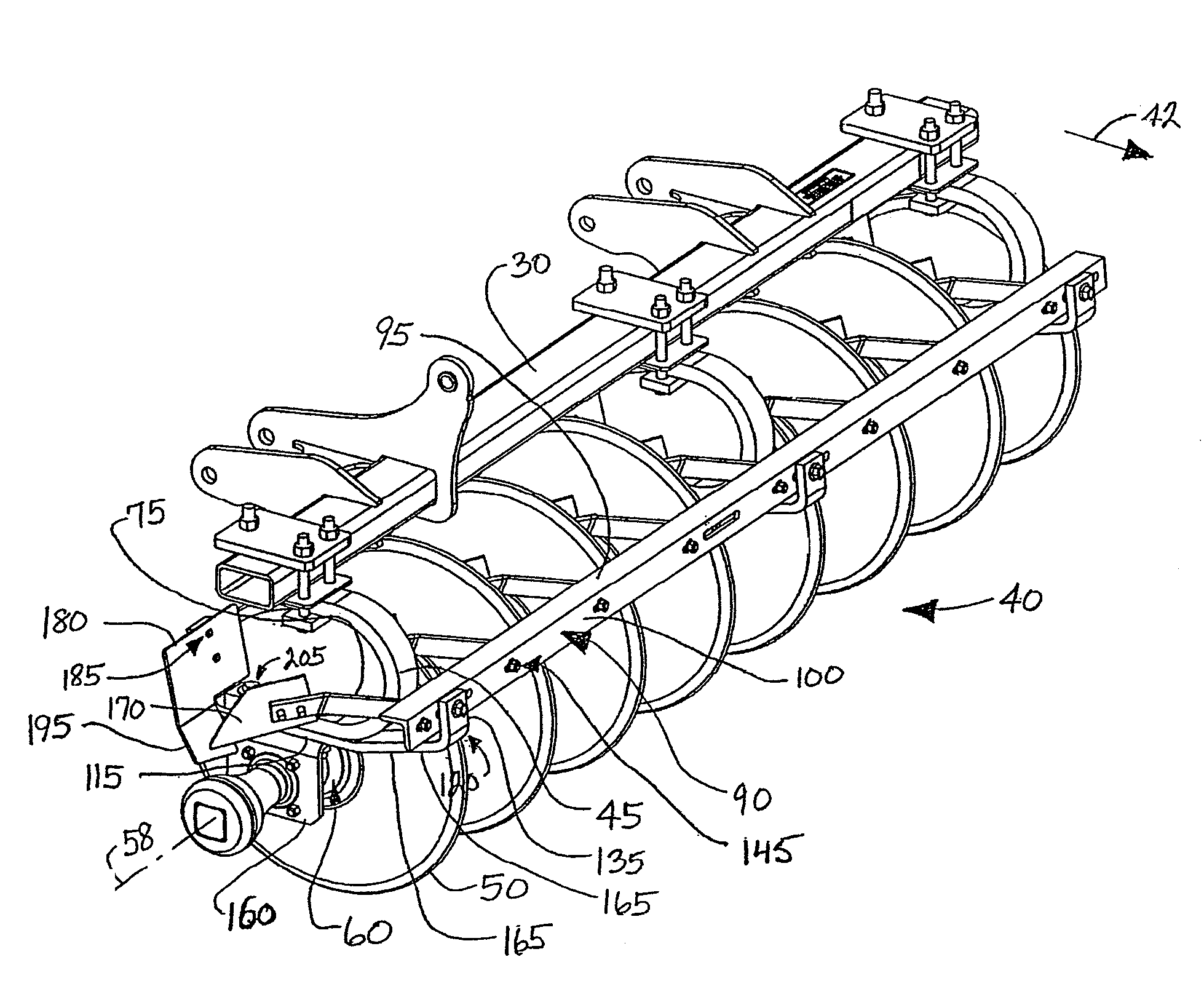
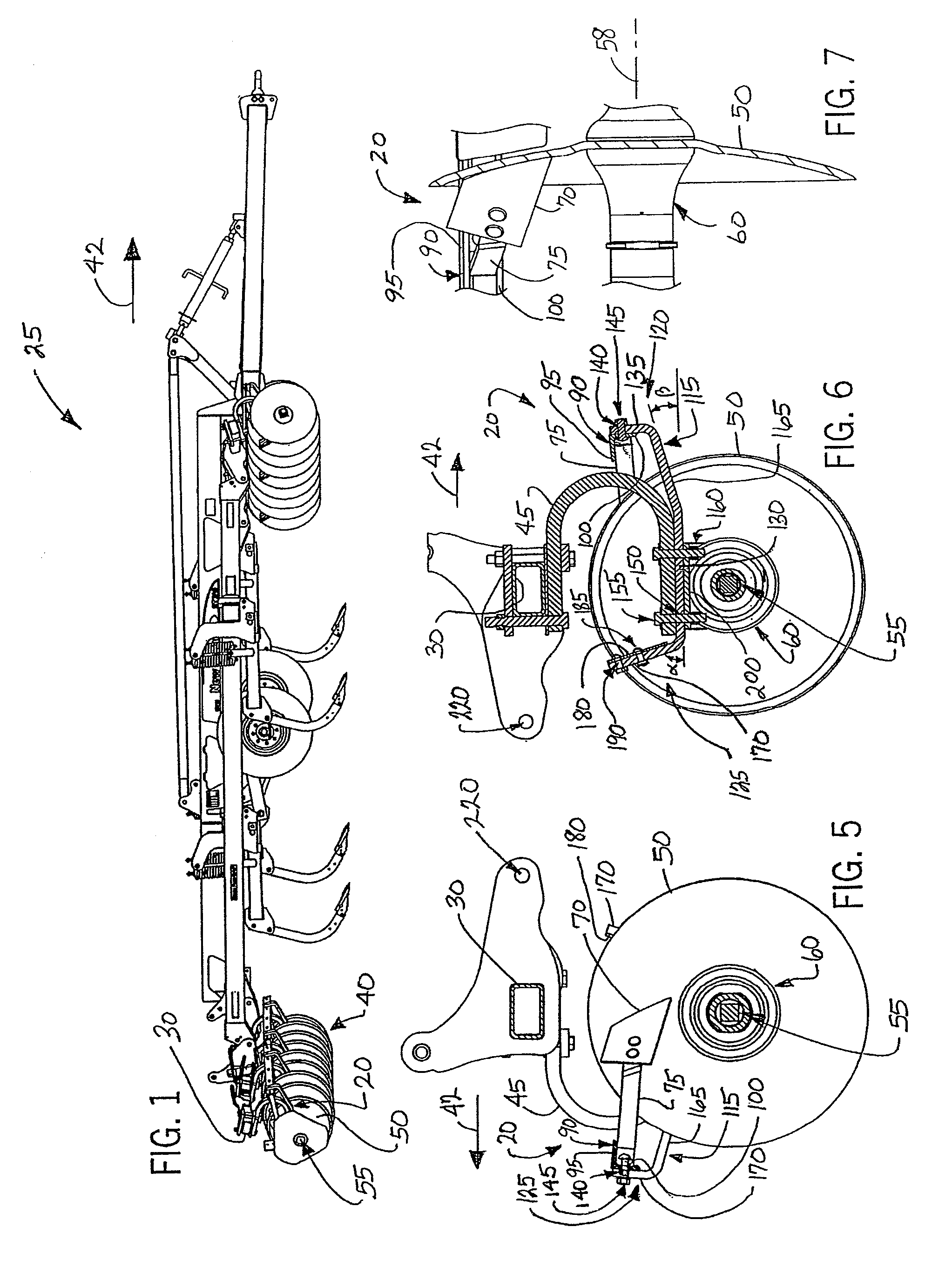
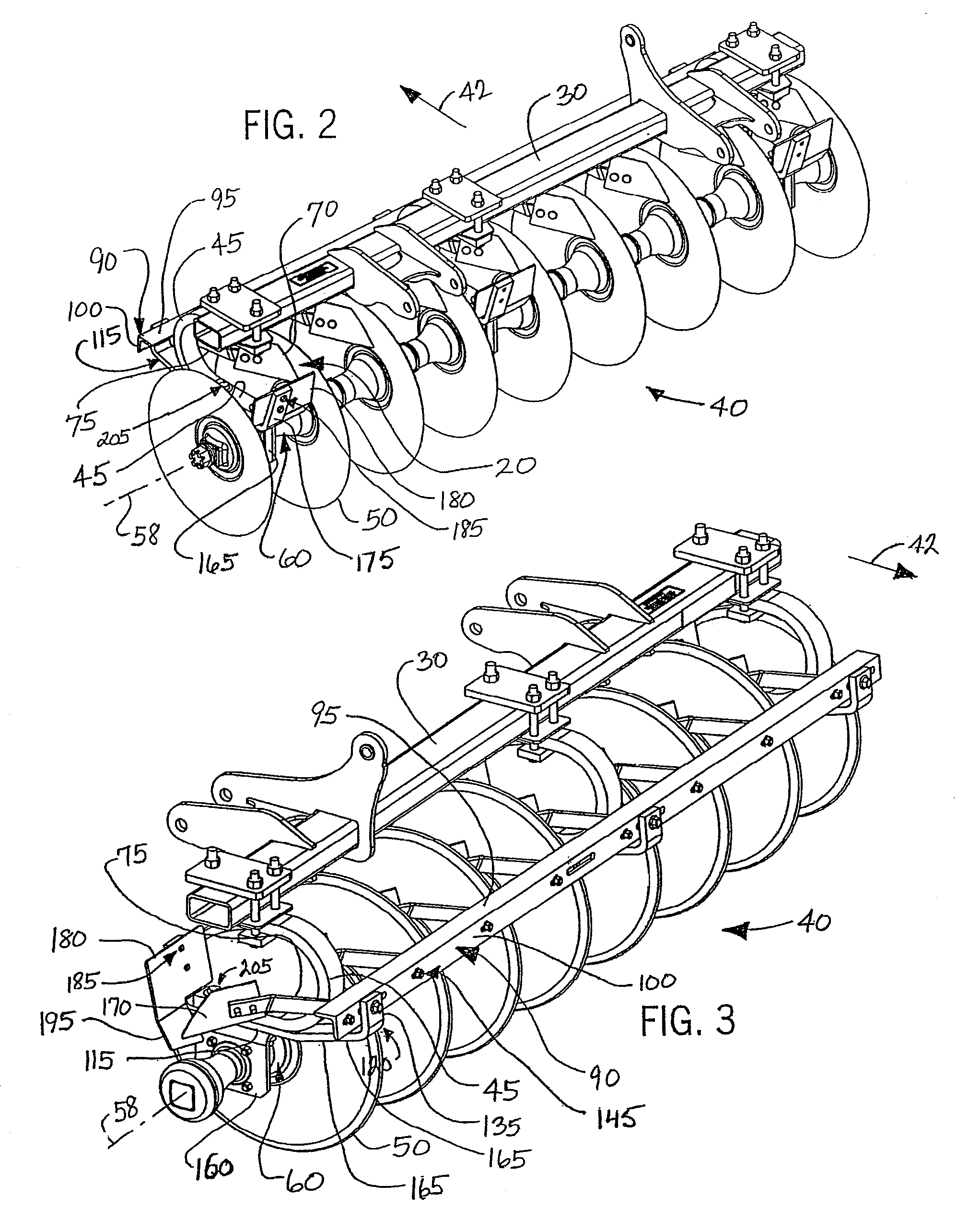
[0022]FIG. 1 shows a preferred embodiment of a scraper system 20 employed on an agricultural tillage or soil working implement 25. The agricultural implement 25 includes a tube or tool bar 30 in support of one or more disc gangs 40 operable to break up lumps and / or clods and / or soil to smaller sized fragments and for smoothing the ground.

[0023]The illustrated agricultural implement 25 is commonly referred to as a disk-ripper-disk (“DRD”) or a mulch ripper disk implement. This implement 25 includes one or more conventional disk gangs 40 at the front and rear of the implement 25, with ripper shanks disposed therebetween. A preferred implement 25 is manufactured by CNH LLC, IH model MRX690 or NH model ST740. The one or more disc gangs 40 are supported from the toolbar 30 so as to be to be towed in a forward direction (illustrated by the arrow and reference 42) over the soil where crop residue or other trash is present. The implement 25 further includes a series of C-shaped spring eleme...


PUM


Abstract

A scraper system to remove and deflect debris and soil from a disc gang mounted on an agricultural implement is provided. The scraper system includes a mounting bracket member supported at a common axle in support of the disc gang. The mounting bracket member is aligned generally parallel to and located forward of the common axle, and is mounted at a forward end of an elongated carry member supported from the common axle. The elongated carry member is generally aligned perpendicular relative to the common axle. A scraper blade is supported by a scraper arm mounted at the mounting bracket member and is located above the common axle. The location of the scrapper blade and the scraper arm allows a deflector plate to be located at the rearward end of the carry member.

Description

FIELD OF THE INVENTION[0001]The invention relates to a scraper system for a disc configuration of an agricultural implement, and more specifically, relates a scraper system that includes a scraper blade and a deflector plate located above a disc gang and a deflector apparatus so as to prevent soil from being lifted upward and over the top of the disc blade gang.BACKGROUND OF THE INVENTION[0002]Agricultural soil preparation equipment typically includes a disc configuration to be used for breaking up and smoothing the surface of cultivated fields in preparation for planting. The disc configuration is usually drawn by a tractor or other source of motor power, multiple disc configurations are often employed, where the forward disc configuration initially breaks up lumps and clods and a rear disc configuration reduces the fragments to still smaller size and smoothing the ground.[0003]A typical disc configuration includes a main frame with several disc gang assemblies suspended therefrom....

Claims


Application Information

Patent Timeline
Patent Type & Authority Patents(United States)
IPC IPC(8): A01B15/16
CPCA01B23/06
Inventor BLUNIER, MELVIN L.KUEBLER, MARVIN D.TETRICK, JAMES L.GERBER, RICKEY L.
Owner BLUE LEAF I P INC
Why Eureka
Try Eureka