
Attachment assembly for firearm handguard and method of attaching handguard to a firearm

a technology of handguards and attachment assemblies, which is applied in the direction of traveller's bags, butts, travelling articles, etc., can solve the problems of handguards being prone to loosening or separating from the firearm, handguards being loose or detached, and posing a risk of injury to users, so as to reduce the movement of handguards

Inactive Publication Date: 2011-10-13
BARNES ANDREW S
View PDF3 Cites 71 Cited by
  • Summary
  • Abstract
  • Description
  • Claims
  • Application Information

AI Technical Summary

Benefits of technology

[0008]According to another embodiment of the invention, the barrel nut includes a knurled section formed on the exterior surface of the barrel nut proximate the second end, and the knurled section facilitates frictional engagement at the interface of the barrel nut and the handguard.
[0014]According to another embodiment of the invention, the barrel nut includes a knurled section formed on the exterior surface of the barrel nut proximate the second end, and the knurled section facilitates frictional engagement at the interface of the barrel nut and the handguard.
[0022]According to another embodiment of the invention, the handguard includes a lug proximate the receiving end whereby the lug engages the upper receiver and minimizes movement of the handguard.

Problems solved by technology

While such handguards offer protection from the hot temperatures generated by firing of the weapon, the handguards can be prone to becoming loose or detached from the firearm due to the force generated when discharging the firearm.
Also, the handguards can become loose or detached due to the rigorous handling of the firearm, such as use in combat related activities.
Sudden unexpected detachment of the handguard from the firearm can render the firearm ineffective and can pose a risk of injury to the user, particularly in combat situations.

Method used


Image

  • Attachment assembly for firearm handguard and method of attaching handguard to a firearm
  • Attachment assembly for firearm handguard and method of attaching handguard to a firearm
  • Attachment assembly for firearm handguard and method of attaching handguard to a firearm

Examples


Embodiment Construction

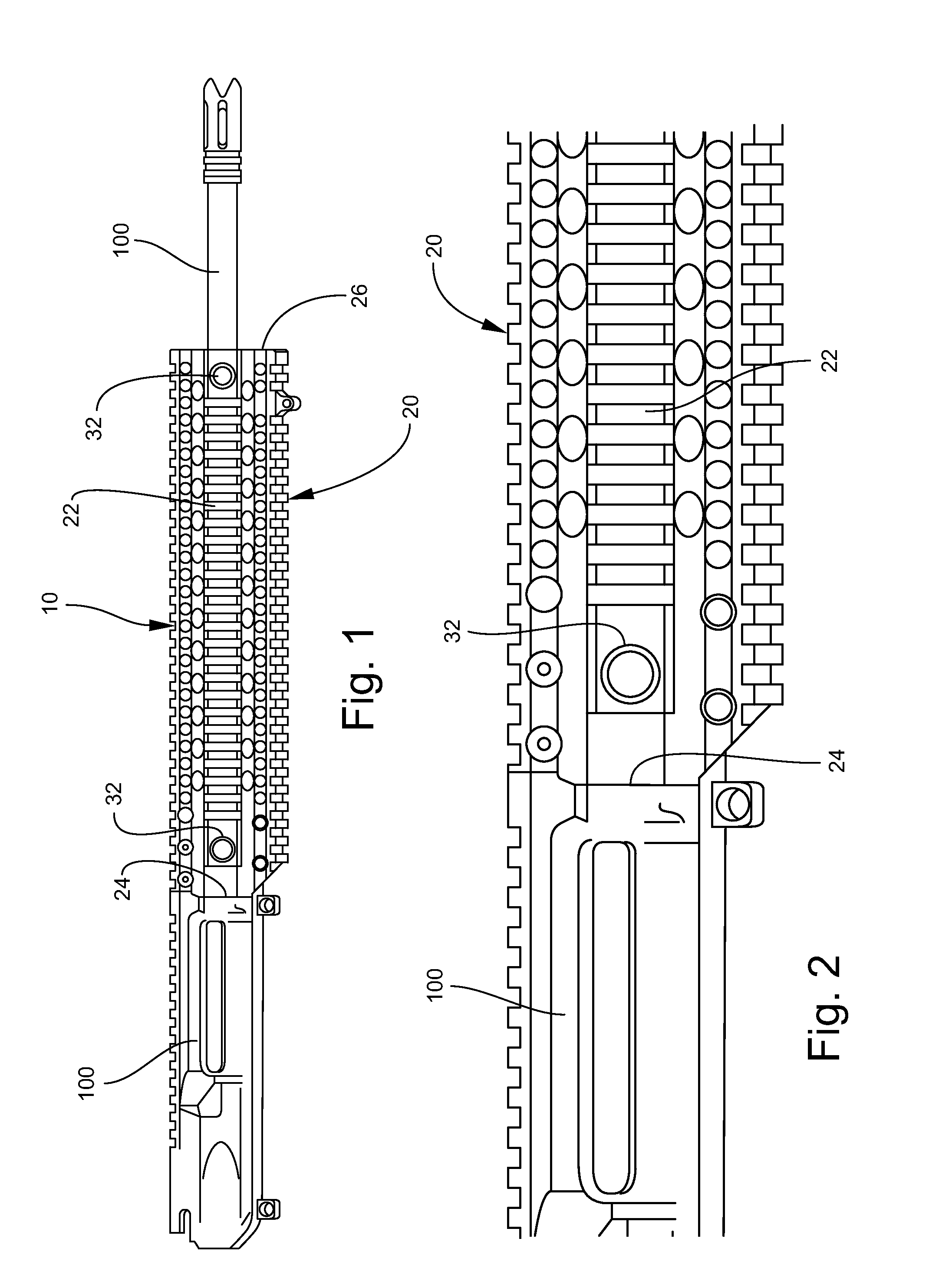
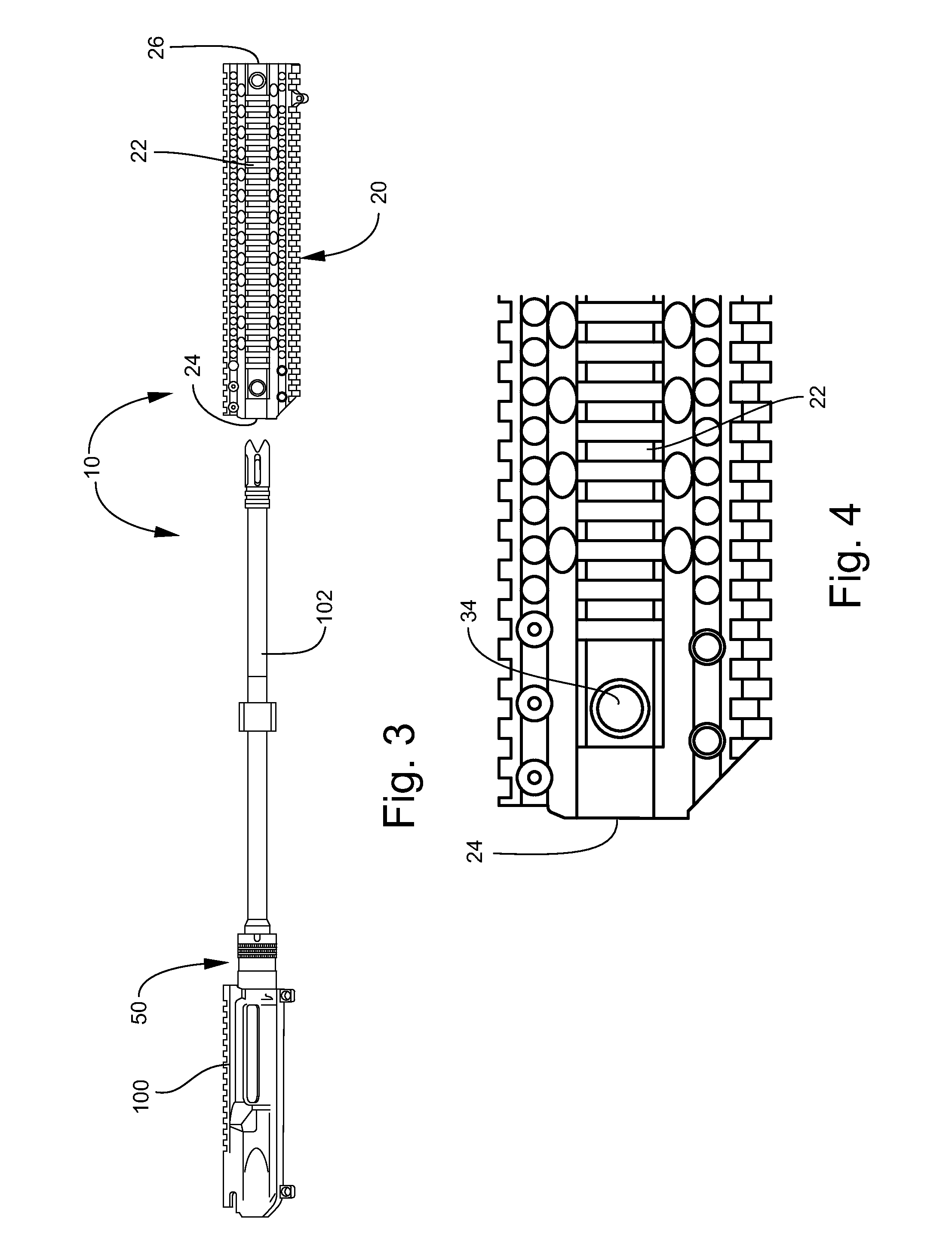
[0040]An attachment assembly for a firearm handguard according to a preferred embodiment of the invention is illustrated in FIGS. 1-3, and shown generally at reference numeral 10. As shown in FIG. 3, the handguard attachment assembly 10 comprises a barrel nut 50 for attaching a handguard 20 to a firearm's upper receiver 100. The handguard 20 includes an elongate rail section 22 with an open receiving end 24 and an open exit end 26, located at opposite longitudinal ends of the rail section 22.

[0041]As shown in FIGS. 5 and 6, the barrel nut 50 is mounted on the barrel 102 of the firearm upper receiver 100. Preferably, the barrel nut 50 is made of steel and can be about 0.875 inch to 8.000 inches in length. Most preferably, the barrel nut 50 is two inches long. As shown in FIGS. 6 and 7, the barrel nut 50 comprises a first section 52 having interior female threads for mating with male threads of the firearm's upper receiver 100. A second section 56 of the barrel nut 50 receives the fir...


PUM


Abstract

An attachment assembly for a firearm handguard includes a barrel nut for mounting on a firearm barrel and engaging the firearm handguard thereon. The barrel nut includes a first end for engaging an upper receiver of a firearm, a second end opposite the first end for receiving the firearm handguard, and a transverse groove formed on an exterior surface of the barrel nut between the first end and the second end, which mechanically locks the firearm handguard on the barrel nut. The barrel nut can include an interior surface with threads formed thereon proximate the first end for engaging complementary threads of the upper receiver. A knurled section can be formed on the exterior surface between the transverse groove and the second end, which provides frictional engagement at the interface of the barrel nut and the handguard.

Description

[0001]This application claims priority to U.S. Provisional Application No. 61 / 323,132, filed Apr. 12, 2010. The present invention relates to handguard attachment assembly for use on a firearm, and a method of attaching a handguard to a firearm. One embodiment of the invention is particularly suited for use with automatic and semi-automatic rifles, such as the M-16, AR-15 and AR-10 rifles.TECHNICAL FIELD AND BACKGROUND OF THE INVENTION[0002]Handguards for use on firearms are known in the art for providing protection to the user from burns that can result from heat generated along the barrel of the firearm during use. While such handguards offer protection from the hot temperatures generated by firing of the weapon, the handguards can be prone to becoming loose or detached from the firearm due to the force generated when discharging the firearm. Also, the handguards can become loose or detached due to the rigorous handling of the firearm, such as use in combat related activities. Sudd...

Claims


Application Information

Patent Timeline
Patent Type & Authority Applications(United States)
IPC IPC(8): F41C23/16F41C23/02A45F5/00F41A21/00
CPCF41A21/48F41C23/16F41A21/482
Inventor BARNES, ANDREW S.
Owner BARNES ANDREW S
Learn More