Cassette for dispensing flexible tubing therefrom

a cassette and flexible tubing technology, applied in the field of cassettes, can solve the problems of cassettes being installed upside down, sanitary and odor problems, and affecting the quality of the product, and achieve the effect of minimizing the likelihood of improper installation of cassettes

a cassette and flexible tubing technology, applied in the field of cassettes, can solve the problems of cassettes being installed upside down, sanitary and odor problems, and affecting the quality of the product, and achieve the effect of minimizing the likelihood of improper installation of cassettes

US20080272140A1Inactive Publication Date: 2008-11-06PLAYTEX PROD INC

Image

  • Cassette for dispensing flexible tubing therefrom
  • Cassette for dispensing flexible tubing therefrom
  • Cassette for dispensing flexible tubing therefrom

Examples


Embodiment Construction

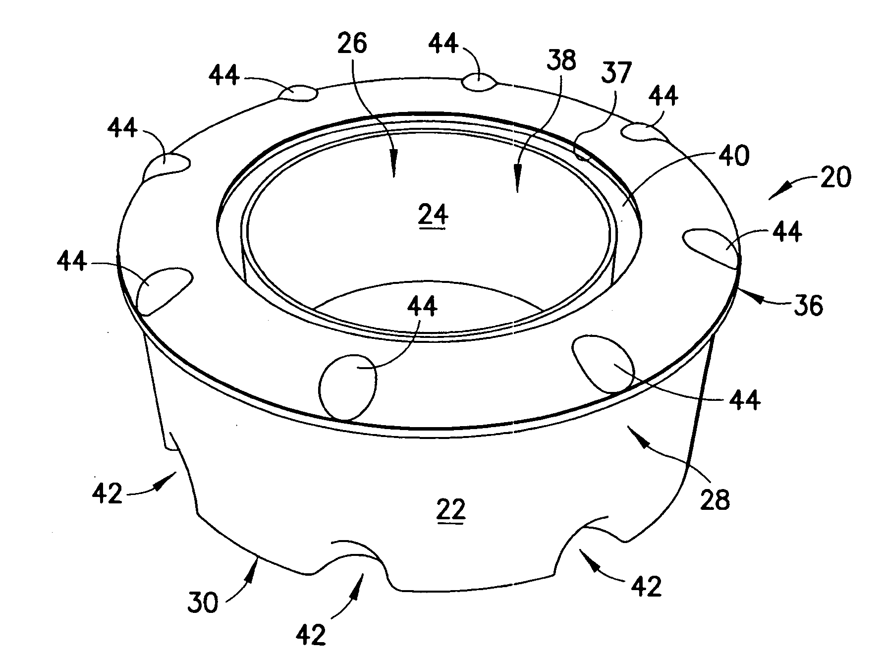
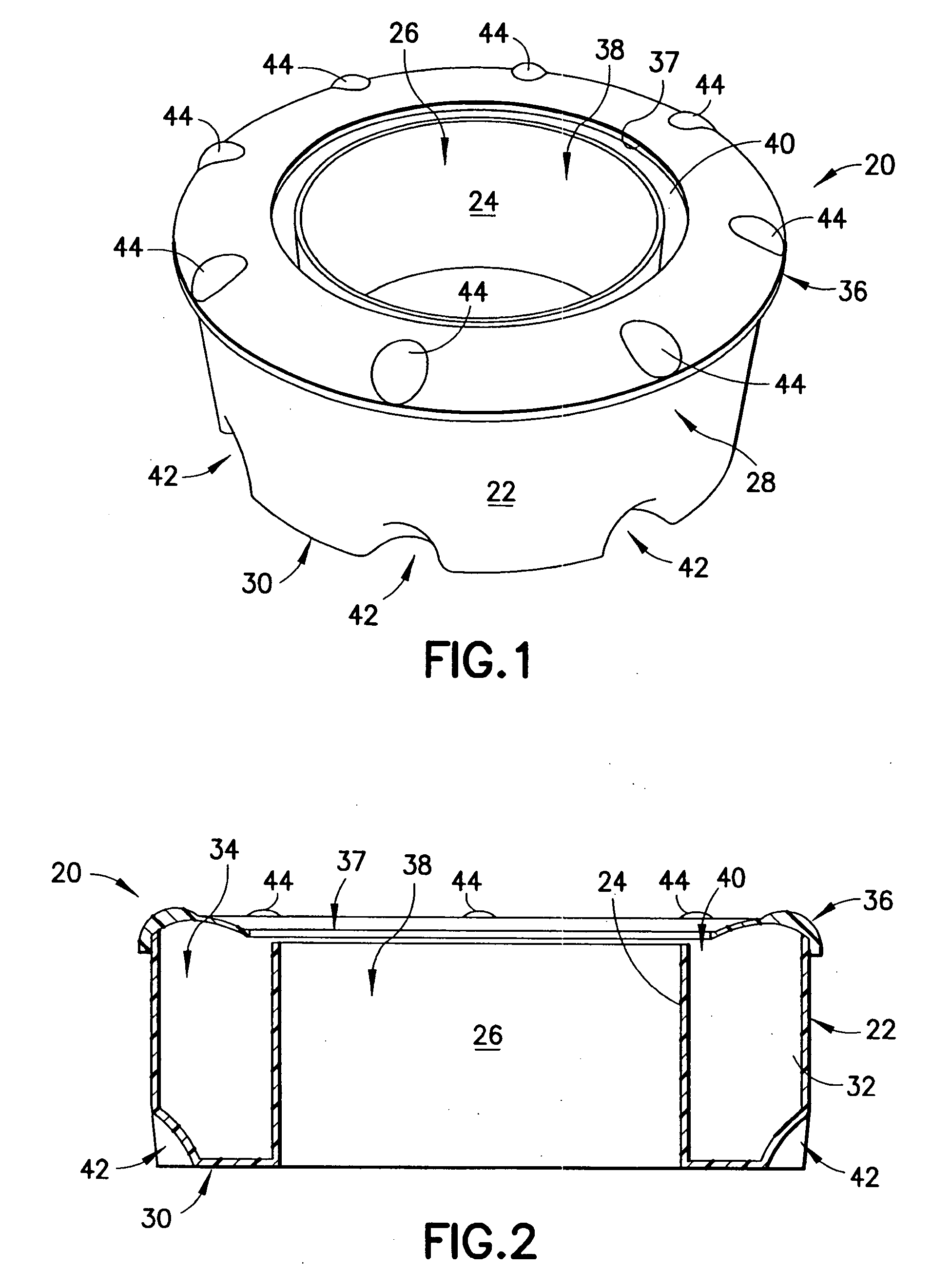
[0027]As shown in FIGS. 1 and 2, a cassette for dispensing plastic tubing is generally designated by the reference number 20. The cassette includes a cassette body generally designated by the reference number 22. The cassette body is defined by a tubular central portion 24 having an aperture 26 extending therethrough. An outer wall 28 surrounds the tubular central portion 24 and is connected thereto by a cassette bottom 30. The tubular central portion 24, the outer wall 28 and the cassette bottom 30 cooperate together to define an interior area 32 into which a length of flexible tubing 34 is operably positioned. A cover generally designated by the reference number 36 is attached to the body 22. The cover 36 has an interior peripheral edge 37 that defines an opening 38 extending through the cover. The opening 38 is sized to form a gap 40 between the tubular central portion 24 and the interior peripheral edge 37 of the cover 24. While the cassette 20 has been shown in the illustrated ...


PUM


Abstract

In a cassette for dispensing flexible tubing a cassette body includes a central tubular portion defining an aperture extending therethrough. An outer wall surrounds the central tubular portion and a cassette bottom extends between and connects the outer wall and the central tubular portion. The outer wall, the cassette bottom and the central tubular portion cooperate to define an interior area that surrounds the central tubular portion. A length of flexible tubing is positioned in the interior area. The cassette bottom includes first registration features and a cover is coupled to the body and at least partially overlies the interior area, the cover defining second registration features matingly engageable with the first registration features so that cassettes can be stacked one-on-top-of-the-other with the cooperation of the first and second registration features preventing successively stacked cassettes from shifting relative to one another.

Description

FIELD OF THE INVENTION[0001]The present invention is generally related to cassettes having plastic tubing therein used in the disposal of waste products such as soiled diapers and is more particularly related to said cassettes having registration features thereon for more efficient stacking as well as to aid in the prevention of improper installation of the cassettes into a receptacle operable therewith.BACKGROUND OF THE INVENTION[0002]Historically, waste materials such as soiled diapers were disposed of by simply placing them in the trash, however, this presented sanitary and odor problems. Moreover, with regard to soiled diapers, these are typically disposed of, albeit temporarily, in the area where the child is changed. Usually this is the nursery where the child sleeps and spends a considerable amount of time. As such, maintaining a sanitary and relatively odor free environment is important.[0003]A number of systems have been developed to address the above-described disposal and...

Claims


Application Information

Patent Timeline
06 Nov 2008
Publication
US20080272140A1
IPC
B65H49/02
CPC
B65F1/062; B65F2240/132; B65F1/14
Inventors
MOWERS, STEPHEN; ROUSSO, JOHN