Construction Machinery Display System and Control Method for Same

a construction machinery and display system technology, applied in the direction of optical elements, instruments, transportation and packaging, etc., can solve the problem of inability to improve the operation efficiency, and achieve the effect of reducing the load on the operator, improving the operation efficiency, and facilitating the operation of working equipmen

Active Publication Date: 2016-07-07
KOMATSU LTD
View PDF8 Cites 79 Cited by
  • Summary
  • Abstract
  • Description
  • Claims
  • Application Information

AI Technical Summary

Benefits of technology

[0016]In the first aspect, the display system, which includes the real image display unit and the combiner, can display the work-support information superimposed on the view in front of the cab. The operator can thus see the working equipment and the work-support information with less movement of his / her eyes. A reduction in the movement of the operator's eyes contributes to an improved operating efficiency.
[0017]Further, based on the position information of the working equipment, the display controller controls the displayed position of the work-support information along the surface of the combiner and the depthwise displayed position of the work-support information defined in the forward direction relative to the cab. The projection image of the work-support information visible to the operator in the cab can thus be displayed around the working equipment, thereby minimizing the movement of the operator's eyes and the adjustment of the focal point of the operator's eyes. This results in a reduction in a load on the operator for seeing the working equipment and the work-support information.
[0018]In the second aspect, the operation information of the working equipment is generated based on the position information of the working equipment, the three-dimensional position information of the body and the target landform information, and displayed as the work-support information. Movement direction and movement amount of the working equipment can thus be displayed as the operation information, so that the operator can easily operate the working equipment.
[0019]In the third aspect, the construction ground information generated based on the three-dimensional position information of the body and the target landform information is displayed in accordance with the geometry and position of the work ground. The operator can thus easily operate the working equipment in accordance with the displayed construction ground information.
[0020]In the fourth aspect, the construction ground information is generated based on the three-dimensional position information of the body, the target landform information, and the work progress information based on the locus information of the working equipment, and displayed in accordance with the geometry and position of the work ground. The operator can thus easily operate the working equipment in accordance with the displayed construction ground information. Further, the operator can see the landform in progress, so that it can be easily checked whether or not the work properly progresses as indicated by the target landform information.
[0021]In the fifth aspect, the lens optical system is disposed between the real image display unit and the combiner. The lens optical system includes the plurality of lenses, at least part of which is movable in the optical axis direction. The display controller moves the at least part of the lenses of the lens optical system in the optical axis direction. The depthwise displayed position of the work-support information is thus easily and promptly controllable.

Problems solved by technology

The operator thus necessarily considerably moves his / her eyes during operating the working equipment, so that an operating efficiency cannot be improved.

Method used


Image

  • Construction Machinery Display System and Control Method for Same
  • Construction Machinery Display System and Control Method for Same
  • Construction Machinery Display System and Control Method for Same

Examples


Embodiment Construction

)

[0039]Exemplary embodiment(s) of the invention will be described below with reference to the attached drawings.

1. Overall Arrangement of Hydraulic Excavator

[0040]Description will be made on a display system for a hydraulic excavator according to an exemplary embodiment (i.e., an example of a display system for a construction machine according to the invention) with reference to the attached drawings.

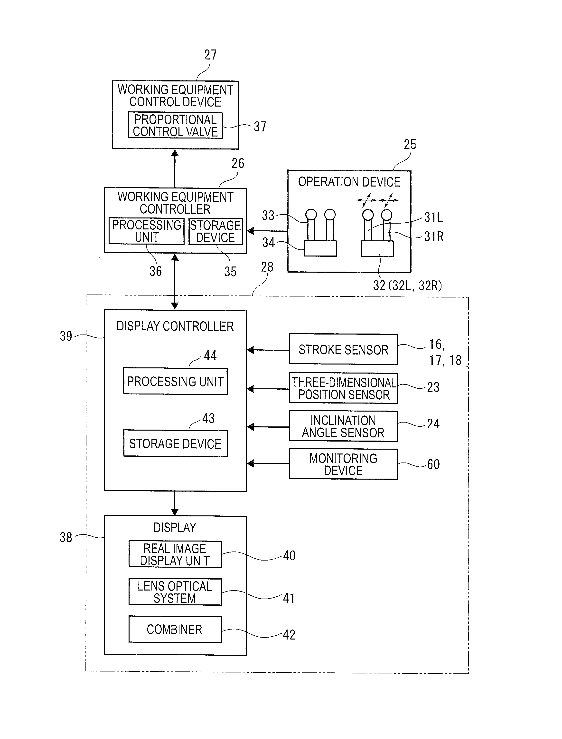
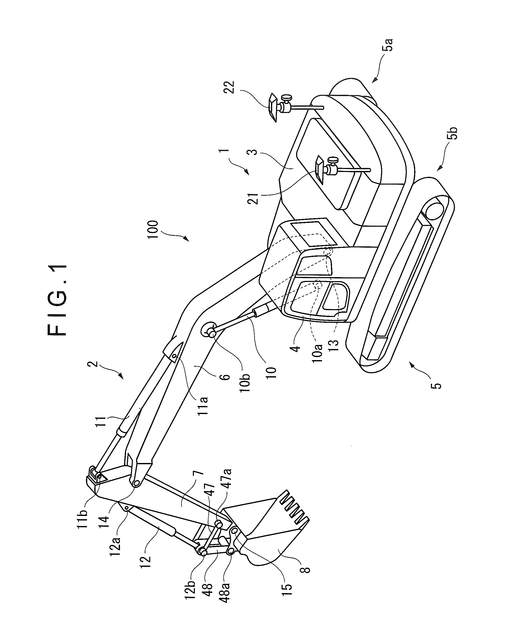
[0041]FIG. 1 is a perspective view showing a hydraulic excavator 100 provided with a display system. The hydraulic excavator 100 includes a vehicle body 1 and working equipment 2. The vehicle body 1 functions as a body according to the invention. The vehicle body 1 includes a rotary upper structure 3, a cab 4 and an undercarriage 5. The upper structure 3 is rotatably mounted on the undercarriage 5. In the upper structure 3, devices such as an engine and a hydraulic pump (not shown) are housed. The cab 4 is provided to a front portion of the upper structure 3. A display 38 and an operati...


PUM


Abstract

The display system includes: stroke sensors that detect position information of working equipment relative to a body; a real image display unit; a combiner; and a display controller. Based on the position information of the working equipment, the display controller controls a displayed position of work-support information along a surface of the combiner and a depthwise displayed position of the work-support information defined in a forward direction relative to a cab. A projection image of the work-support information visible to an operator is thus displayed around the working equipment.

Description

TECHNICAL FIELD[0001]The present invention relates to a display system for a construction machine and a control method of the display system.BACKGROUND ART[0002]In the field of construction machines such as a hydraulic excavator, a technique of displaying various information such as the temperature of an engine cooling water on a monitor in a cab is known (see, for instance, Patent Literature 1).[0003]Further, a technique of displaying an image showing a designed geometry of a work ground and the position of a blade edge of a bucket on a monitor in a cab is also known (see, for instance, Patent Literature 2).CITATION LISTPatent Literature(s)[0004]Patent Literature 1: JP-A-2012-136985[0005]Patent Literature 2: JP-A-2012-172431SUMMARY OF THE INVENTIONProblem(s) to be Solved by the Invention[0006]The monitor is provided to a lower part of a vertical frame separating a front window and a side window of the cab so as not to reduce an operator's field of forward view (see FIG. 2 of Patent...

Claims


Application Information

Patent Timeline
Patent Type & Authority Applications(United States)
IPC IPC(8): B60K35/00E02F9/26E02F9/16
CPCB60K35/00B60K2350/352E02F9/264E02F9/16E02F9/261G06T11/00G02B27/0101B60K2370/52
Inventor TSUBONE, DAIKURIHARA, TAKASHIFUKANO, RYO
Owner KOMATSU LTD
Why Eureka
Try Eureka