Adjustable lighting fixture for sloped ceiling

a technology for lighting fixtures and slopes, applied in fixed installations, lighting and heating equipment, lighting support devices, etc., can solve the problems of difficult adjustment of lighting, and difficulty in adjusting lighting, etc., to achieve the effect of easy adjustment of lighting

Inactive Publication Date: 2009-02-03
PHILIPS LIGHTING NORTH AMERICA CORPORATION
View PDF131 Cites 60 Cited by
  • Summary
  • Abstract
  • Description
  • Claims
  • Application Information

AI Technical Summary

Benefits of technology

[0011]The optics assembly further comprises a yoke assembly and a reflector. The yoke assembly comprises an adjustable yoke in which the reflector is housed so that the yoke and the reflector move in concert. The yoke assembly further comprises at least one secondary support piece, which is preferably stationary. The secondary support piece has a curved track opening into which a connector fits, thereby forming a hinge where the yoke and the secondary support piece are attached. When the connectors slide along the curved track opening, the yoke and the reflector move along an axis defined by the hinge so that the optics assembly is easily adjusted.

Problems solved by technology

Unfortunately, the slope of a ceiling as designed often does not precisely match the slope of the ceiling after it has been built.
As a result, lighting fixtures designed for ceilings sloped at a particular angle do not lead to perfectly aligned optics assemblies even when markings are employed to facilitate the process.
Since the installment and adjustment of ceiling lights usually requires a person to climb up a ladder and work in high places, the process is physically awkward, time-consuming, tedious, and somewhat dangerous.

Method used


Image

  • Adjustable lighting fixture for sloped ceiling
  • Adjustable lighting fixture for sloped ceiling
  • Adjustable lighting fixture for sloped ceiling

Examples


Embodiment Construction

[0022]While this invention is capable of embodiments in many different forms, multiple embodiments are shown in the figures and will be herein described in detail. The present disclosure is to be considered an exemplification of the principles of the invention and is not intended to limit the broad aspects of the invention to the embodiments illustrated.

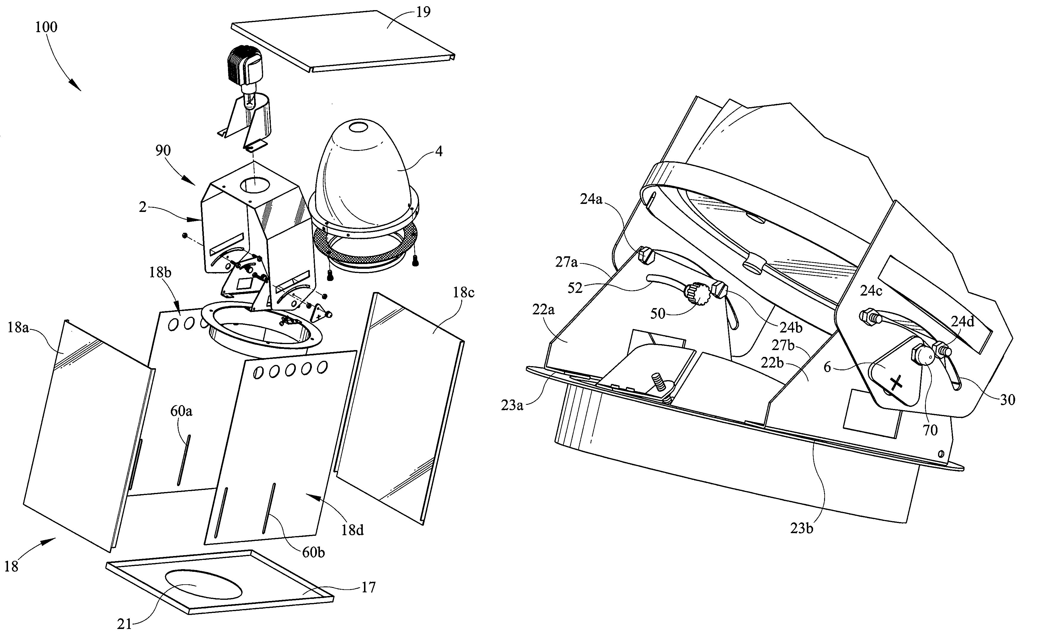
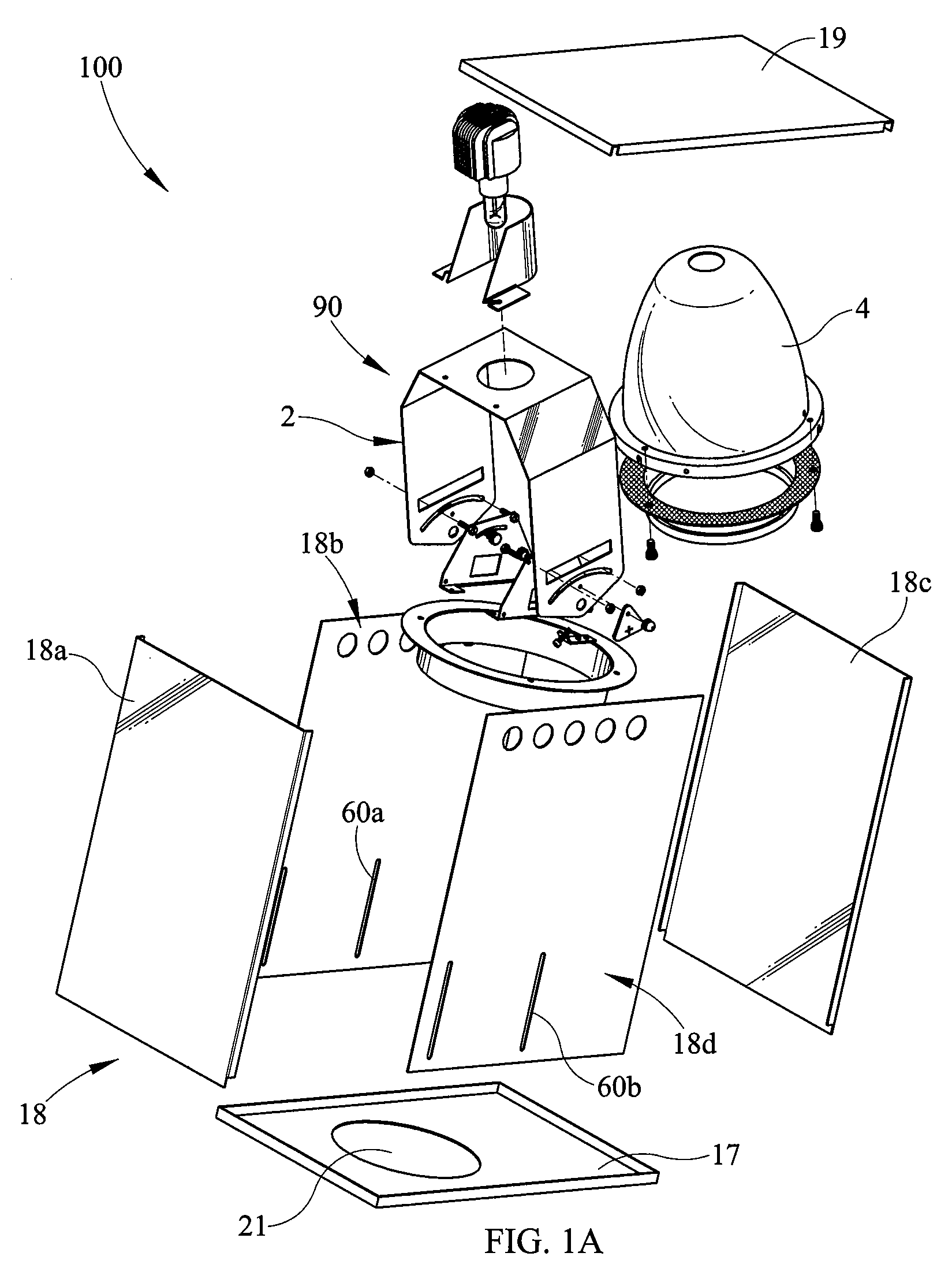
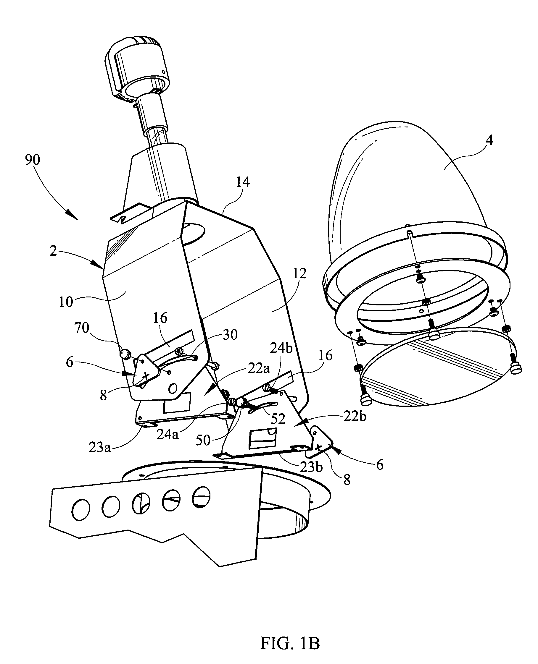
[0023]Referring now to the drawings and initially to FIGS. 1a-1c, a lighting fixture 100 for a sloped ceiling comprises an enclosure 18, an optics assembly comprising a reflector 4 and a yoke assembly 2 (FIGS. 1a-1b) that guides the movement of the reflector 4, and at least one gravity-controlled pendulum 6 (FIGS. 1a-c, FIG. 2) to indicate when the optics assembly is properly aligned.

[0024]For recessed lighting fixtures to perform optimally, their optics assemblies must point downward. The force of gravity always pulls the gravity-controlled pendulum 6 downward, which makes it easier to identify when the optics assembly is aligned co...


PUM


Abstract

The invention provides a lighting fixture for a sloped ceiling comprising an enclosure, an optics assembly situated within the enclosure, and at least one gravity-controlled pendulum with an indicator capable of being used to align the optics assembly. The lighting fixture further comprises a yoke assembly comprising a yoke and a secondary support piece, and at least one connector that guides the movement of the yoke.

Description

CROSS-REFERENCE TO RELATED APPLICATIONS[0001]Not applicableBACKGROUND OF THE INVENTION[0002]1. Field of the Invention[0003]The present invention relates to a lighting fixture for a sloped ceiling, whose position can be easily adjusted. More particularly, the present invention relates to a lighting fixture having an optics assembly and a gravity-controlled pendulum with an indicator that facilitates correct positioning of the optics assembly.[0004]2. Background of the Invention[0005]Many residential and commercial buildings have rooms with sloped ceilings. Lighting fixtures recessed within the ceiling are often used to light these rooms in an effective and inconspicuous way. To perform optimally, it is important that the optics assemblies of these lighting fixtures be properly aligned in a vertical position. These fixtures typically have optics assemblies that are adjustable for use with ceilings having a particular slope. The fixtures have markings that aid a person in aligning them...

Claims


Application Information

Patent Timeline
Patent Type & Authority Patents(United States)
IPC IPC(8): F21V15/00
CPCF21S8/02F21V21/30
Inventor BUSE, JOHN JEFFREY
Owner PHILIPS LIGHTING NORTH AMERICA CORPORATION
Why Eureka
Try Eureka