Illumination device having elliptical body and display device using the same

a technology of elliptical body and display device, which is applied in the direction of lighting and heating apparatus, planar/plate-like light guides, instruments, etc., can solve the problems of leaking more light to the outside from the light guiding portion, the difficulty of realizing a thinner illumination device or a thinner display device, etc., and achieves the effect of efficiently propaga

Active Publication Date: 2009-02-03
DAWNCREST IP LLC
View PDF16 Cites 27 Cited by
  • Summary
  • Abstract
  • Description
  • Claims
  • Application Information

AI Technical Summary

Benefits of technology

[0008]According to the present invention, an illumination device includes a light source, a light incident body, and a light guide plate coupled to the light incident body at an end portion for evenly emitting light, which is incident from the light incident body, from a light emitting surface. The light incident body has a light incident surface opposing the light source and is perpendicular to a light emitting surface of the light guide plate, and the outside shape of the light incident body between the light incident surface and the light guide plate is oval. This structure allows efficient coupling between a light source of a conventional size and a thin light guide plate thinner than the light source. Even propagating light is repeatedly reflected inside the light incident body, the light can propagate efficiently into the thin light guide plate without a considerable influence on the distribution of the angle of incidence with respect to the light guide plate.
[0009]Further, the light incident surface of the light incident body is formed so as to be located between an anterior focal point on the side of the light source and the center of the oval portion forming the light incident body, while a coupling portion between the light incident body and the light guide plate is formed so as to be located near another focal point, a posterior focal point. This arrangement allows light which passes near one of the focal points to, after being reflected by the oval surface of the light incident body, pass near the other focal point, and thus, light emitted from the light source can propagate efficiently into the light guide plate.
[0010]Further, the illumination device is formed such that a light emitting surface of the light source is located between the anterior focal point and the light incident surface. With such a structure, since light emitted from the light source in the light incident body is substantially equivalent to light emitted from near the anterior focal point, light emitted from the light source can propagate efficiently into the light guide plate.

Problems solved by technology

However, since it is difficult to make thinner an LED as the light source, it is difficult to realize a thinner illumination device or a thinner display device.
In an illumination device having a conventional wedge-like light guiding portion, the angle of incidence of propagating light with respect to a reflecting surface becomes greater as the light is repeatedly reflected by the inner surfaces of the light guiding portion, so the amount of light propagating through the light guide plate with the angle of incidence being greater than the critical angle decreases, and thus, light cannot be efficiently guided from the light source to the light guide plate.
Further, a greater angle of incidence of propagating light results in a greater amount of leakage light to the outside from the light guiding portion and adjacent areas.
Therefore, unevenness in brightness and stray light increase, and satisfactory illumination cannot be carried out.
Thus, if a group of conventional parallel sawtooth prisms are formed on the light guide plate, it is difficult to form an even distribution of emitted light.

Method used


Image

  • Illumination device having elliptical body and display device using the same
  • Illumination device having elliptical body and display device using the same
  • Illumination device having elliptical body and display device using the same

Examples


embodiment 1

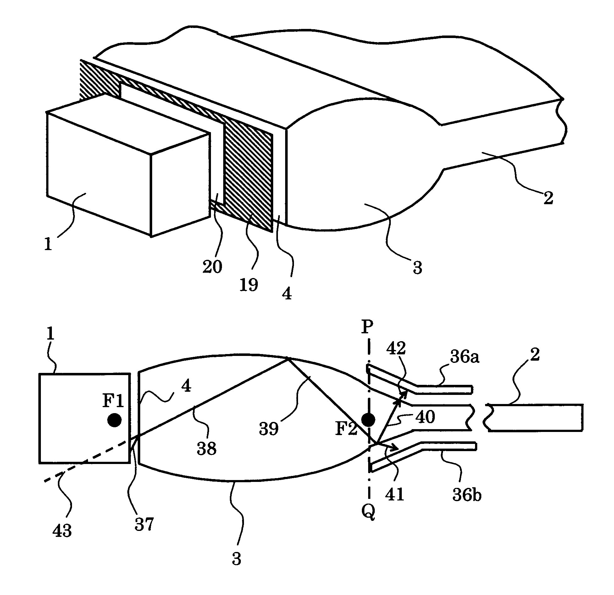
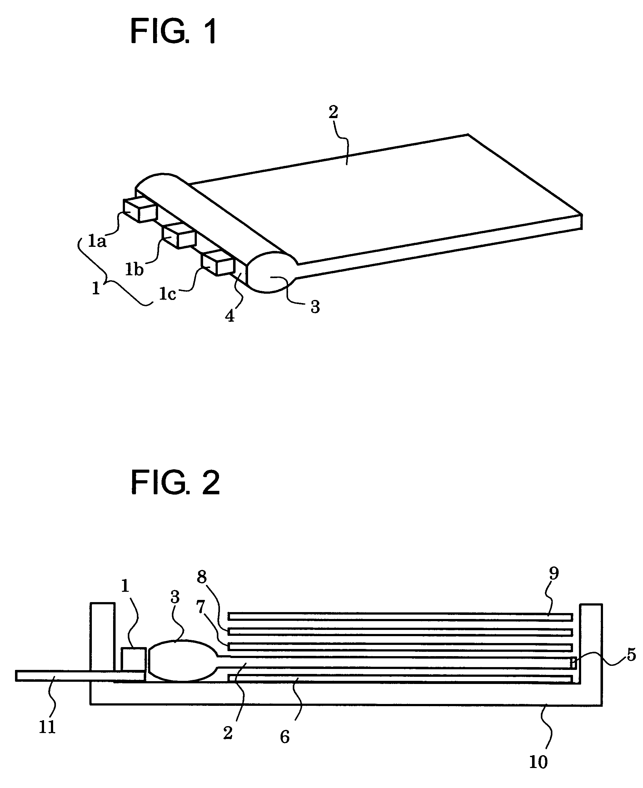
[0057]An illumination device according to the present invention is described in the following with reference to attached drawings. FIG. 1 is a perspective view schematically illustrating the illumination device according to the present invention. In FIG. 1, a light incident body 3 is coupled to a light guide plate 2 at an end portion. A light incident surface 4 is formed at the other end face of the light incident body 3 opposite to the side of the light guide plate 2. A plurality of light sources la, lb, and lc are arranged so as to oppose the light incident surface 4. The light incident body 3 and the light guide plate 2 are integrally formed as a one-piece structure by injection molding, and micro-structures for light-scattering (not shown) are formed on a surface of the light guide plate 2 which surface is opposite to a light emitting surface of the light guide plate 2. The light incident body 3 and the light guide plate 2 are not required to be integral in so far as the two are...

specific example 1

[0098]As shown in FIG. 1, three white LEDs as the light source were arranged along the light incident surface to make the illumination device according to the present invention. The height of the light emitting surfaces of the white LEDs was 0.5 mm. The light guide plate having a size of 35 mm in width and 40 mm in length was used. The ratio of the major axis to the minor axis of the oval surface of the light incident body was 6.7. The distance between the light incident surface and the light emitting surface of the white LEDs was about 0.7 mm, and the light incident surface was 0.5 mm in height. Further, a polymer tape with an Al film vapor deposited on a surface on the side of the light guide plate thereof was attached on the surfaces on the side of the light guide plate and of the light incident body except the surface of the light guide plate opposing the light incident surface.

[0099]First, as illustrated in FIG. 8, a sample was prepared where the light guide plate and the light...

specific example 2

[0106]With regard to Sample 3 in Specific Example 1 which is 300 μm thick, concave micro-structures for light-scattering were formed on the underside of the light guide plate within the light guide plate, the micro-structures for light-scattering being right triangles in shape in cross section where the base and the height of the triangle were about 10 μm×30 μm and about 7 μm, respectively (Sample 4). The density of the formed micro-structures for light-scattering was made higher as the distance from the white LEDs increased such that the intensity of light emitted from the light emitting surface of the light guide plate was even.

[0107]For comparison, an illumination device using a conventional flat light guide plate which did not have the light incident body according to the present invention was prepared (Comparative Sample 2). The thickness of the light guide plate of Comparison Sample 2 was 300 μm, and the same micro-structures for light-scattering as those of Sample 4 were form...


PUM


Abstract

An illumination device for emitting light includes a light incident body having a first end portion that has a light incident surface on which light from a light source is incident, a second end portion, and an outer oval-shaped surface portion interconnection the first and second end portions. A light guide plate is optically coupled to the second end portion of the light incident body and has a light emitting surface through which light that propagates through the light incident body is emitted. The light guide plate and the light incident body are integrally formed and may comprise a one-piece body. A display device utilizes the illumination device for illuminating a display element of the non-self light emitting type.

Description

BACKGROUND OF THE INVENTION[0001]1. Field of the Invention[0002]The present invention relates to an illumination device for use in a mobile phone, a portable TV set, a hand-held game machine, a personal digital assistant (PDA), and a notebook personal computer, and to a display device using the same.[0003]2. Description of the Related Art[0004]Known examples of a conventional illumination device which is called a backlight or a frontlight include a side light type illumination device in which a plurality of LED light sources are disposed on a side of a light guide plate as the light source. For example, an illumination device for use in a portable information device such as a mobile phone is required to be thinner. However, since it is difficult to make thinner an LED as the light source, it is difficult to realize a thinner illumination device or a thinner display device. One approach to solving the problem is disclosed in JP 2000-249837 A where a wedge-like light guiding portion c...

Claims


Application Information

Patent Timeline
Patent Type & Authority Patents(United States)
IPC IPC(8): F21V7/08
CPCG02B6/002G02B6/4206G02B6/4298G02B6/0036G02B6/0061G02B6/0068H04M1/22
Inventor DEJIMA, NORIHIROKURIHARA, MAKOTOSADO, TAKAYASUHONMA, KATSUNORI
Owner DAWNCREST IP LLC
Why Eureka
Try Eureka