
Circuit and method for pulse width modulation by means of synchronized, self-oscillating pulse width modulators

a pulse width modulator and pulse width technology, applied in pulse position modulation, pulse combined modulation, pulse technique, etc., can solve the problems of additional problems, distortion of the output signal of the pwm modulator, and variations of the switching frequency

Active Publication Date: 2009-02-03
MAXLINEAR INC
View PDF6 Cites 5 Cited by
  • Summary
  • Abstract
  • Description
  • Claims
  • Application Information

AI Technical Summary

Benefits of technology

The invention describes techniques for synchronizing multiple self-oscillating PWM modulators. This is achieved through a synchronization circuit that generates an auxiliary signal that is coupled into the modulators. The auxiliary signal can be generated based on the input signal levels or the signal centers of the modulators. The synchronization circuit can also correct frequency errors or mismatches between the modulators. Additionally, the invention describes a three-valued pulse width modulator that combines the output signals of two self-oscillating pulse width modulators. The invention also includes a circuit arrangement that includes a digital data pump, digital / analog converter, and a pulse width modulator circuit with two self-oscillating pulse width modulators and a synchronization circuit.

Problems solved by technology

One problem in self-oscillating PWM modulators consists in that variations of the switching frequency can occur.
Variations of the switching frequency lead to distortions in the output signal of the PWM modulator.
If a number of channels of a system are to be processed by means of a number of self-oscillating PWM modulators, additional problems arise due to the lack of synchronism of the self-oscillating PWM modulators.

Method used


Image

  • Circuit and method for pulse width modulation by means of synchronized, self-oscillating pulse width modulators
  • Circuit and method for pulse width modulation by means of synchronized, self-oscillating pulse width modulators
  • Circuit and method for pulse width modulation by means of synchronized, self-oscillating pulse width modulators

Examples


Embodiment Construction

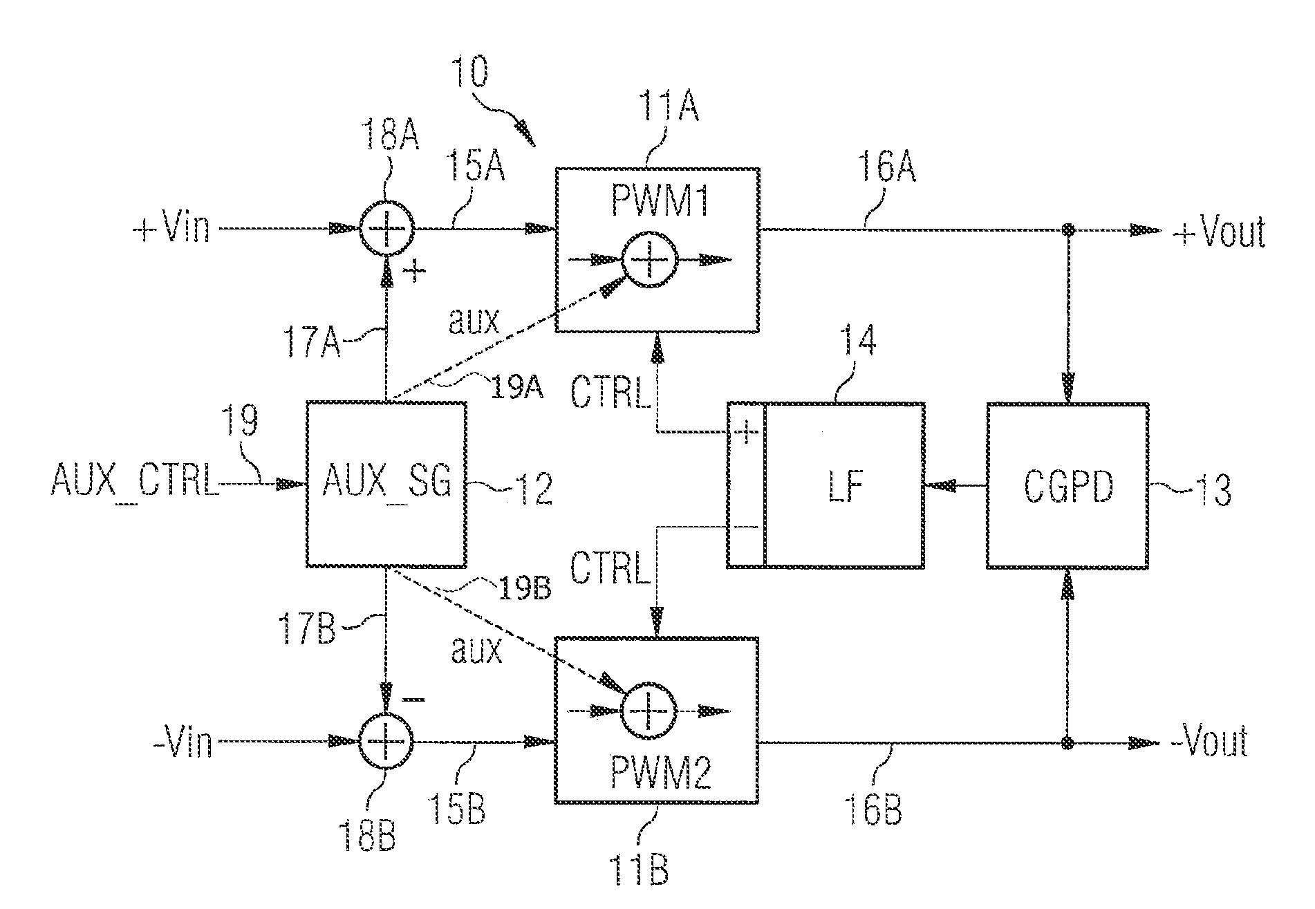
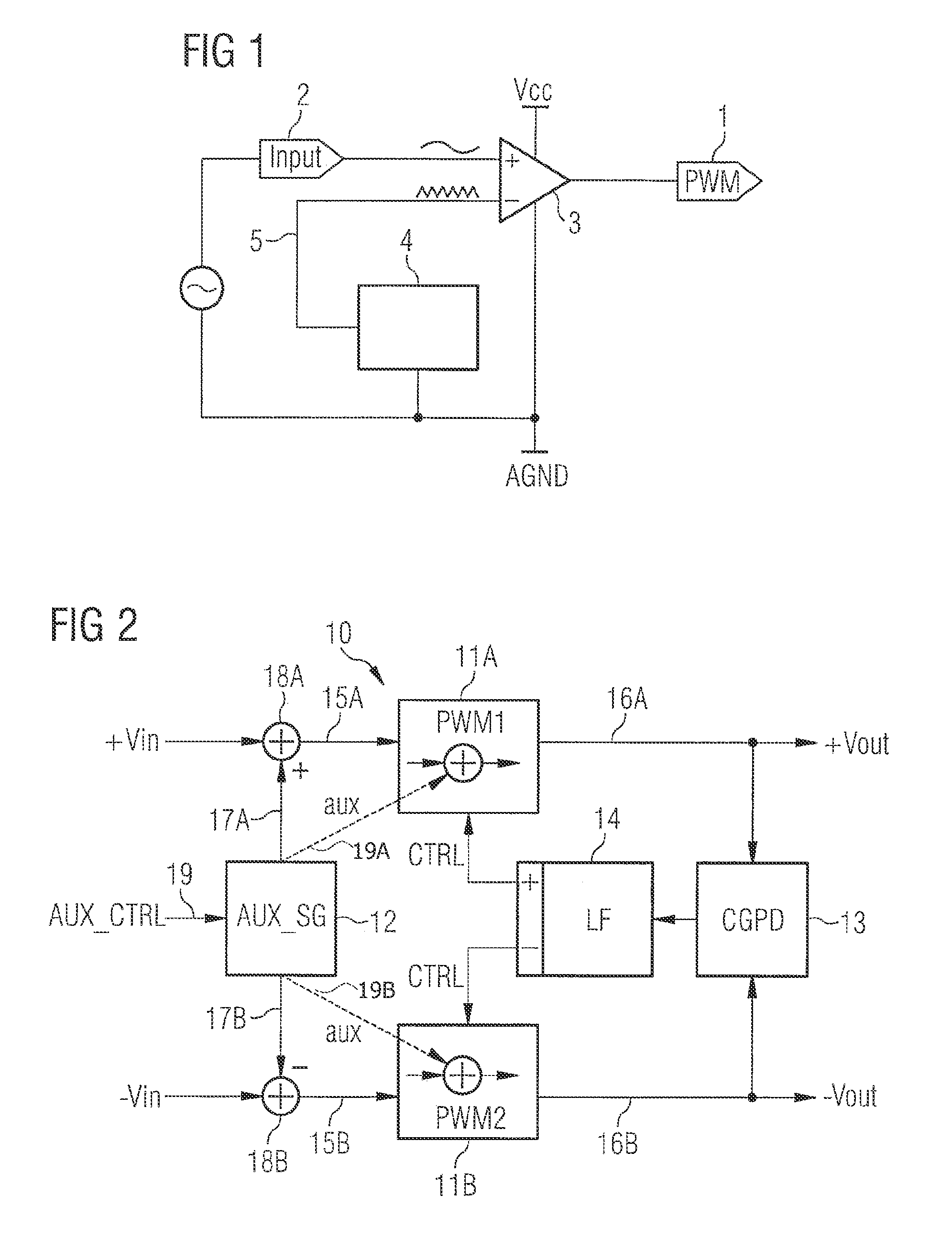
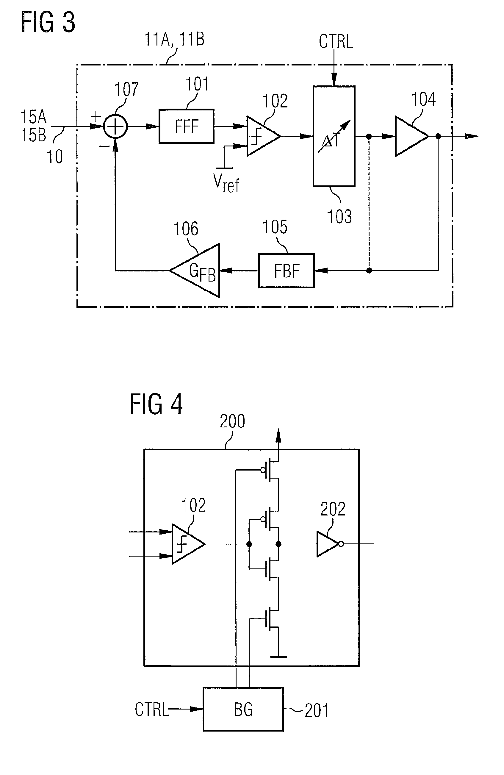
[0032]According to FIG. 2, a pulse width modulator circuit 10 according to a first illustrative embodiment comprises a first PWM modulator PWM111A, a second PWM modulator PWM211B, an auxiliary-signal generating circuit aux_SG 12, a center of gravity phase detector CGPD 13 and a loop filter LF 14. The first PWM modulator 11A is supplied with a usually analog input signal 15A, the second PWM modulator 11B receives a usually analog input signal 15B. The PWM modulators 11A, 11B are self-oscillating PWM modulators which provide pulse-width-modulated output signals +Vout and −Vout, respectively, via output signal lines 16A, 16B.

[0033]The required synchronization of the PWM modulators 11A, 11B is effected, for example, via the center of gravity phase detector 13 and the loop filter 14, the structure and operation of which will be described later. As an alternative to the synchronization via the center of gravity phase detector 13 and the loop filter 14, shown in FIG. 2, the synchronization...


PUM


Abstract

A pulse width modulator circuit has two self-oscillating pulse width modulators and a synchronization circuit for synchronizing the two self-oscillating pulse width modulators. It also comprises an auxiliary-signal generating circuit for generating an auxiliary signal which is coupled into the two self-oscillating pulse width modulators.

Description

[0001]This application claims priority to German Patent Application 10 2006 026 906.3, which was filed Jun. 9, 2006 and is incorporated herein by reference.TECHNICAL FIELD[0002]The invention relates to circuits and methods for pulse width modulation by using synchronized, self-oscillating pulse width modulators. The invention can be used for converting power in a plurality of systems, particularly in line drivers, audio amplifiers and switched-mode power supplies.BACKGROUND[0003]Pulse width modulators convert an analog input signal into a sequence of pulses, the pulse length of which is proportional to the amplitude of the input signal. Due to the value discreteness of the output signal, pulse width modulation (PWM) provides for high efficiency of the power conversion and offers high linearity.[0004]Conventional PWM modulators use a clock generator which predetermines the switching frequency of the PWM modulator. FIG. 1 illustrates a basic circuit for generating a PWM signal 1 from ...

Claims


Application Information

Patent Timeline
Patent Type & Authority Patents(United States)
IPC IPC(8): H03K7/08H03K7/04
CPCH03F3/217H03K7/08H03F2200/351
Inventor CLARA, MARTINWIESBAUER, ANDREASPOETSCHER, THOMASSEGUNDO BELLO, DAVID SANWALTER, SERGIO
Owner MAXLINEAR INC
Learn More