
An infrared anechoic chamber for simulation of wide-spectrum directional coupling optical systems in near space and outside the atmosphere in the laboratory

A near-space, directional coupling technology, applied in the field of infrared anechoic chamber, can solve the problem of reducing the dynamic range of information acquisition, achieve the effect of improving contrast, improving simulation effect, and suppressing stray radiation

Active Publication Date: 2020-08-28
HARBIN INST OF TECH
View PDF7 Cites 0 Cited by
  • Summary
  • Abstract
  • Description
  • Claims
  • Application Information

AI Technical Summary

Problems solved by technology

[0004] The purpose of the present invention is to solve the problem that the existing method will reduce the dynamic range of information acquisition when simulating a wide-spectrum directional coupling optical system, and to provide an infrared darkroom for a wide-spectrum directional coupling optical system, which can pass Low-temperature vacuum simulates the real space environment near space and outside the atmosphere

Method used


Image

  • An infrared anechoic chamber for simulation of wide-spectrum directional coupling optical systems in near space and outside the atmosphere in the laboratory

Examples


specific Embodiment approach 1

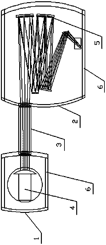
[0014] Specific Embodiment 1: This embodiment records an infrared darkroom for a wide-spectrum directional coupling optical system. The infrared darkroom is composed of a low-temperature cold tank A1, a low-temperature cold tank B2, a docking window 3, and a receiving system 4 Composed of a wide-spectrum directional coupling optical system 5;

[0015] The low-temperature cold tank A1 and the low-temperature cold tank B2 are docked through the docking window 3, the receiving system 4 is located in the low-temperature cold tank A1, and the wide-spectrum directional coupling optical system 5 is located in the low-temperature cold tank B2 Inside.

specific Embodiment approach 2

[0016] Specific embodiment two: a kind of infrared anechoic chamber for wide-spectrum directional coupling optical system described in specific embodiment one, described low-temperature cold tank A 1 and low-temperature cold tank B 2 are both in a vacuum state, and the specific vacuum degree It can be adjusted according to the simulation needs.

specific Embodiment approach 3

[0017] Specific embodiment three: a kind of infrared anechoic chamber for wide-spectrum directional coupling optical system described in specific embodiment one, described low-temperature cold tank A 1 and low-temperature cold tank B 2 both have an interlayer 6, and low-temperature cold tank A 1 The interlayer 6 of the interlayer 6 and the interlayer 6 of the low-temperature cold tank B2 are all filled with liquid nitrogen refrigeration. The refrigeration temperature is 100K.


PUM


Abstract

The invention discloses an infrared darkroom for a wide-spectrum directional coupling optical system, and belongs to the technical field of infrared target and background simulation. The infrared darkroom comprises a low-temperature cold tank A, a low-temperature cold tank B, a butting window, a receiving system and a wide-spectrum directional coupling optical system, wherein the low-temperature cold tank A and the low-temperature cold tank B are butted through the butting window, the receiving system is positioned in the low-temperature cold tank A, and the wide-spectrum directional couplingoptical system is positioned in the low-temperature cold tank B. The infrared darkroom provided by the invention has the advantages that stray radiation is inhibited by adopting a low temperature, anda dynamic range of acquired information is not lost. The infrared darkroom provided by the invention can improve the contrast of long-distance and weak point source targets and improve the simulationeffect. The infrared darkroom provided by the invention can provide a vivid low-temperature vacuum condition for optical system simulation in a near space and outside the atmosphere, and effectivelyrestrain stray radiation of the optical system and improve the contrast of a target on the premise of ensuring the dynamic range of acquired information.

Description

technical field [0001] The invention belongs to the technical field of infrared target and background simulation, and in particular relates to an infrared darkroom for a wide-spectrum directional coupling optical system. Background technique [0002] The wide-spectrum directional coupling optical system can receive the infrared radiation emitted by the infrared characteristic generating device of the target and accompanying objects in a vacuum, low-cooling and normal temperature environment, and perform directional beam expansion, recombination, registration, and re-collimation of the outgoing beams of each channel. Realize the complex connection between the multi-channel separation exit pupil of the target and accompanying object infrared characteristic generation device and the detection system entrance pupil, provide infinite multi-target composite scenes, and have the function of extracting low-cold targets, providing wide-band large-bandwidth for vacuum low-radiation sim...

Claims


Application Information

Patent Timeline
Patent Type & Authority Patents(China)
IPC IPC(8): G01N21/01G01N21/03
CPCG01N21/01G01N21/03
Inventor 张建隆郭鑫民
Owner HARBIN INST OF TECH
Learn More