Large-caliber secondary imaging R-C optical system
A secondary imaging and optical system technology, applied in the field of infrared imaging, can solve the problems of multiple stray light, unable to meet the efficiency of cold aperture and so on
- Summary
- Abstract
- Description
- Claims
- Application Information
AI Technical Summary
Problems solved by technology
Method used
Image
Examples
Embodiment 1
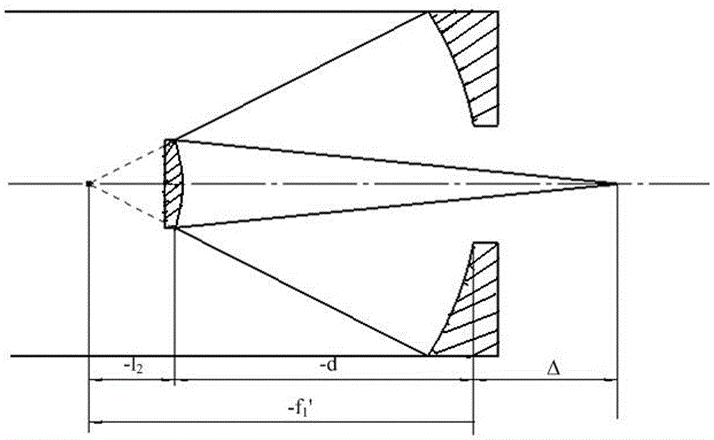
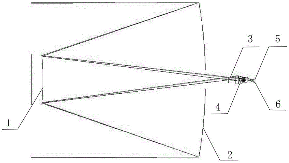
[0042] A large-aperture secondary imaging R-C optical system, the R-C optical system is sequentially provided with a hyperboloid mirror 1, an aperture stop 2, a field stop 3, a secondary transfer lens group 4 and a cold stop 5, and all mirror surfaces Coaxial setting, hyperboloid reflector 1, aperture stop 2, and field stop 3 form a primary imaging system to achieve primary imaging convergence for external scenes. The converging surface is located on the field stop 3, and the secondary transfer lens group 4 The secondary imaging system is composed of the cold diaphragm 5, and the secondary imaging is performed on the converging light plane of the field diaphragm 3, and the obtained spectral imaging is located on the image plane 6.
[0043] The secondary image conversion lens group 4 includes four lenses, viewed from the direction of the field stop 3 to the cold stop 5, the first meniscus lens 7, the second meniscus lens 8, the biconcave lens 9 and the biconvex lens 10, The fie...
Embodiment 2
[0065] A large-aperture secondary imaging R-C optical system, the R-C optical system is sequentially provided with a hyperboloid mirror 1, an aperture stop 2, a field stop 3, a secondary transfer lens group 4 and a cold stop 5, and all mirror surfaces Coaxial setting, hyperboloid reflector 1, aperture stop 2, and field stop 3 form a primary imaging system to achieve primary imaging convergence for external scenes. The converging surface is located on the field stop 3, and the secondary transfer lens group 4 The secondary imaging system is composed of the cold diaphragm 5, and the secondary imaging is performed on the converging light plane of the field diaphragm 3, and the obtained spectral imaging is located on the image plane 6.
[0066] The secondary image conversion lens group 4 includes four lenses, viewed from the direction of the field stop 3 to the cold stop 5, the first meniscus lens 7, the second meniscus lens 8, the biconcave lens 9 and the biconvex lens 10, The fie...
experiment example
[0088] Taking Embodiment 46 as an example, the optical path diagram of the infrared detection optical system in the ZEMAX software is as follows image 3 as shown, Figure 4 It is the enlarged picture of the secondary relay lens group. After the first imaging of the two-mirror R-C system, the second imaging is performed. The exit pupil of the imaging system coincides with the cold screen, so that the entrance pupil of the primary mirror and the cold diaphragm are in common The yoke can better suppress stray radiation and improve the signal-to-noise ratio.
[0089] Figure 5 In order to complete the modulation transfer function diagram of the designed infrared detection optical system, the function value fully reflects the design and evaluation results of the system. With the increase of the field of view, the modulation transfer function value is gradually decreasing. Among them, the modulation transfer function value of the edge field of view is still better than 0.48, indi...
PUM
| Property | Measurement | Unit |
|---|---|---|
| Caliber | aaaaa | aaaaa |
Abstract
Description
Claims
Application Information
 - R&D
- Intellectual Property
- Life Sciences
- Materials
- Tech Scout
- Unparalleled Data Quality
- Higher Quality Content
- 60% Fewer Hallucinations
Browse by: Latest US Patents, China's latest patents, Technical Efficacy Thesaurus, Application Domain, Technology Topic, Popular Technical Reports.
© 2025 PatSnap. All rights reserved.Legal|Privacy policy|Modern Slavery Act Transparency Statement|Sitemap|About US| Contact US: help@patsnap.com


