
Anti-vibration mechanism for dental impression material mixer

a technology of anti-vibration and dental impression, which is applied in the direction of shock absorbers, machine supports, transportation and packaging, etc., can solve the problems of affecting the product quality of denatured products, rough surface, and impression materials that cannot be mixed evenly, and achieve the effect of enhancing the stability of the motor

Active Publication Date: 2009-02-10
WANG SHU LUNG
View PDF9 Cites 22 Cited by
  • Summary
  • Abstract
  • Description
  • Claims
  • Application Information

AI Technical Summary

Benefits of technology

"The present invention provides an anti-vibration mechanism for a dental impression material mixer. The mechanism includes supporting poles, elastic springs, a base plate, and a restricting board. The elastic springs connect the supporting poles to the motor, and the restricting board restricts the position of the motor. The mechanism absorbs the vibration produced by the motor, enhancing the stability of the motor and its mounted mechanisms during operation. The technical effect of the invention is to improve the stability and efficiency of the dental impression material mixer during use."

Problems solved by technology

Since the above mixture will solidify and set within a period of time, therefore, owing to the time constraints for manual stirring, the impression materials usually cannot be mixed evenly.
Furthermore, the way of stirring manually is quite strenuous and will cause the mixture to form bubbles, thus causing the cast to retain air holes within which results in a rough surface.
This defect will greatly affect the product quality of the denatures.
Since the stirring method for dental impression materials is basically manual, there is no specific mixer available.
Such a defect will eventually affect the operation stability of the motor 14 and every mechanism mounted on top.

Method used


Image

  • Anti-vibration mechanism for dental impression material mixer
  • Anti-vibration mechanism for dental impression material mixer
  • Anti-vibration mechanism for dental impression material mixer

Examples


Embodiment Construction

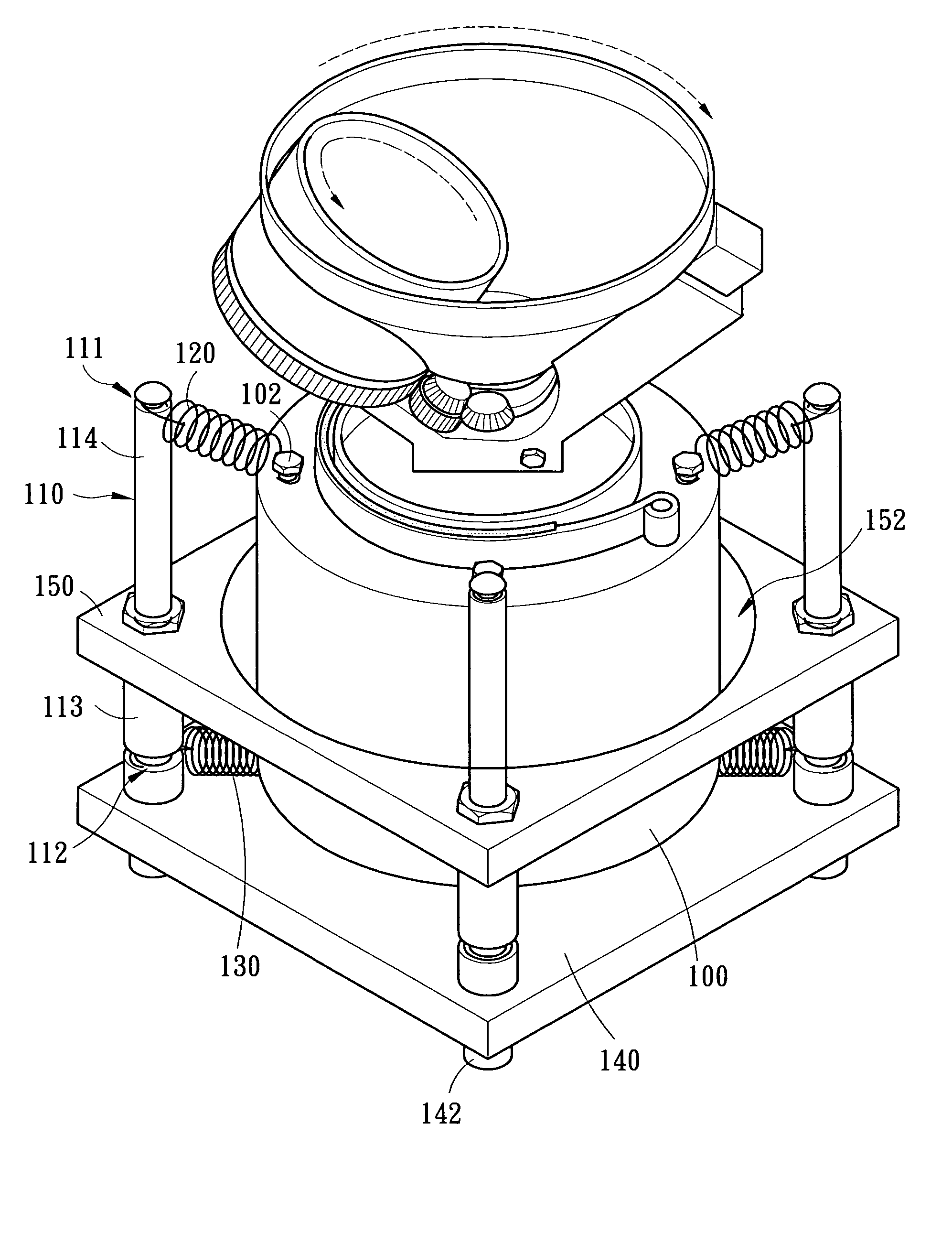
[0014]Firstly, please refer to FIGS. 3 to 5 simultaneously. The anti-vibration mechanism for dental impression material mixer of the preferred embodiment of the present invention, mainly includes a plurality of supporting poles 110, a plurality of first elastic springs 120, a plurality of second elastic springs 130, a base plate 140 and a restricting board 150.

[0015]The first elastic spring 120 connects a corresponding position at the top end of an adjacent supporting pole 110 and the top of a motor 100. According to this preferred embodiment, a first notch portion 111 is designed near the top end of each supporting pole 110. One end of the first elastic spring 120 can be fastened on the first notch portion 111 so as to link the supporting pole 110. The top of the motor 100 is mounted with a plurality of fixed members 102 (such amount is equal to the number of the first elastic springs 120). The other end of each first elastic spring 120 can be clasped on the corresponding fixed mem...


PUM


Abstract

An anti-vibration mechanism for dental impression material mixer. The mechanism includes a plurality of supporting poles, a plurality of first elastic springs, a plurality of second elastic springs, a base plate and a restricting board. One end of both the first elastic spring and the second elastic spring are linked to the supporting pole, and the other end is linked to the top and the bottom of a motor respectively. The position of the motor is restricted at a central opening of the restricting board, and the motor is hanging above the base plate. Since the present invention is mainly dependent on the resilient elongation of the first elastic spring and the second elastic spring, which are linked on the top and the bottom of the motor respectively the present invention are absorb the vibration when the motor is operating and enhance the stability of the motor and every mechanism mounted on its top.

Description

FIELD OF THE INVENTION [0001]The present invention relates to an anti-vibration mechanism and, more particularly, to an anti-vibration mechanism for a dental impression material mixer.BACKGROUND OF THE INVENTION [0002]In the practice of dentistry, a cast or a mold must be made according to the profile of the patient's teeth during the manufacturing of dentures, and then the dentures are formed according to the cast. The ingredients of the cast are generally chosen from impression materials or plaster. After adding water to these ingredients, the whole mixture is then stirred manually until it has a sticky texture for further utilization. Since the above mixture will solidify and set within a period of time, therefore, owing to the time constraints for manual stirring, the impression materials usually cannot be mixed evenly. Furthermore, the way of stirring manually is quite strenuous and will cause the mixture to form bubbles, thus causing the cast to retain air holes within which r...

Claims


Application Information

Patent Timeline
Patent Type & Authority Patents(United States)
IPC IPC(8): F16M1/00F16M11/00F16M3/00F16M5/00F16M7/00F16M9/00
CPCB01F9/0001F16F15/067B01F29/10
Inventor WANG, SHU-LUNG
Owner WANG SHU LUNG
Learn More