Slip fit quick disconnect pipe coupler

a quick disconnect and pipe coupler technology, applied in the direction of hose connections, screw connections, liquid fuel engines, etc., can solve the problem of user pulling against this frictional for

Active Publication Date: 2009-02-10
WEBER PATENT HLDG
View PDF24 Cites 5 Cited by
  • Summary
  • Abstract
  • Description
  • Claims
  • Application Information

AI Technical Summary

Benefits of technology

[0016]The insertion portion has a flange constructed to mate with said channel. That is, the flange width, breadth, and length is substantially equivalent to the width, breadth, and length of the housing portion channel. In a preferred embodiment, the insertion portion has a first face with a groove having an O-ring or elastomeric gasket, all of which mates with a second face on said housing portion. The unique channel width taper assures a force placement between said faces and onto said O-ring which is substantially perpendicular to said channel and which provides compression of said O-ring and assured sealing between the insertion and housing portion.
[0017]Although the tapered fit between the insertion and housing portions provides a secure holding action, unique to the delineated applications, retention of the respective portions is assured since the insertion opening is typically at a higher elevation than the channel vertex. That is in a preferred embodiment, since within a well, cistern, or sump application the supply pipe having a submerged pump is vertically connected with said pipe coupling portion on said insertion portion, gravitational force promotes continuous seating of the two portions. An alternative embodiment of the present art has a latch mechanism or assembly which assures a secure mating of the two portions in an inverted position.
[0018]In the preferred embodiment, the insertion portion has an integral strap member forming a substantial orifice into which a simple substantially L-shaped removal tool may be placed for separation of the two portions. Unique to the present invention, an opening within said orifice allows protrusion of a bridge on said housing portion into said orifice whereby a slight prying force of said removal tool will separate or “pop” the two portions apart. Once initially separated, the tapered fit is no longer placing said force to create O-ring compression and the two portions easily separate. This allows the plumbing technician or user to easily separate or “pop” the two portions apart and then simply lift the pump and supply pipe or other components without any additional force other than that caused by the weight of the supply pipe and pump. Prior art devices without this uniquely tapered mating configuration require the user to lift against the frictional interface for the full length of the slip coupling.
[0019]An alternative embodiment of said removal or decoupling tool is formed of a tubular steel with a substantially L-shape having a lever end and a decoupling end. Said decoupling end inserts into the pipe coupler orifice which allows the operator to apply force against the pipe coupler bridge of said pipe coupler, thereby decoupling said pipe coupler. Said decoupling end further comprises a strap member retainer and a ball. Said ball is of a weight and size which allows rolling of said ball within said tubular decoupling end. Said decoupling end further comprises a window on said inner surface to allow said strap member retainer to extend beyond an inner surface of said decoupling end. Said decoupling end further comprises pivot points whereby said strap member retainer is pivotally mounted. Said lever end is of sufficient length to allow an operator to apply adequate force for decoupling said pipe connecter and for extraction of said pipe components. Said lever end further comprises eyes or holes capable of accepting one or more handles. Said handles aid in applying addition force, or assist the operator in extracting said supply pipe after decoupling.
[0020]Operation of said decoupling tool is by means of canting said decoupling tool against a pipe coupler bridge, thereby applying force until decoupling take place. Gravitational force will cause said ball to roll against said strap member retainer, forcing said strap member retainer to an extended position. Once said strap member retainer is extended, the pipe coupler strap member is prevents the decoupling tool from slipping off said coupler. When said strap member retainer is retracted via an opposition cant said decoupling tool may be withdrawn, thereby securely extracting said supply pipe.

Problems solved by technology

Unfortunately, when separating the prior art, the user must pull against this frictional force during the entire separation process.

Method used


Image

  • Slip fit quick disconnect pipe coupler
  • Slip fit quick disconnect pipe coupler
  • Slip fit quick disconnect pipe coupler

Examples


Embodiment Construction

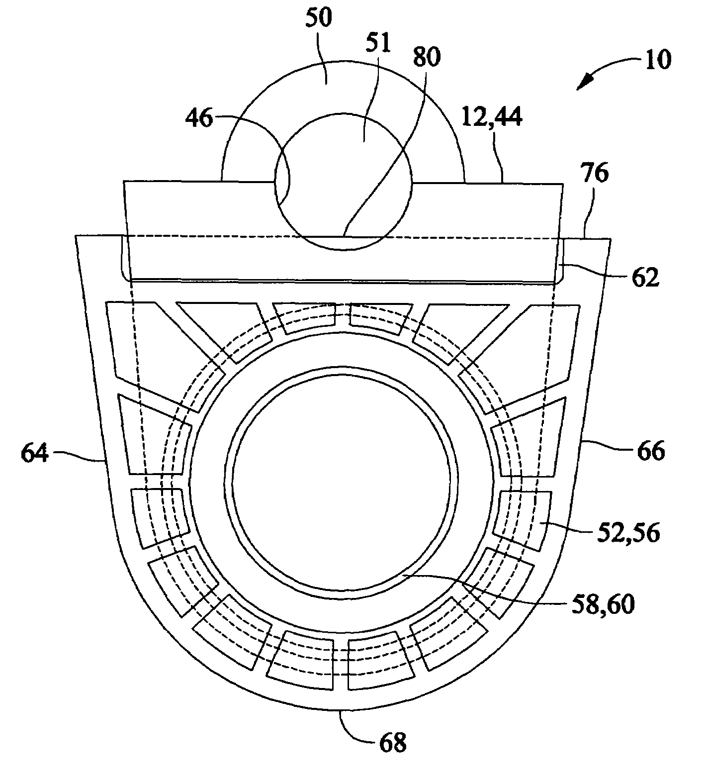
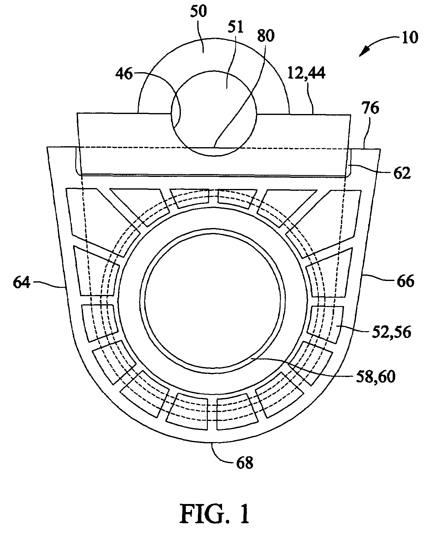
[0064]Referring now to the drawings, there is shown in FIGS. 1-41 a preferred embodiment of a slip fit quick disconnect pipe coupler10 and the removal tool 84. The device 10 is particularly adapted for quick coupling and repeated disconnection of any types of pipes, especially within septic pump tanks, wells, cisterns, sumps, industrial pits, and other liquid storage facilities including swimming pool equipment. Said pipes may be of any material including but not limited to metallic and polyvinyl chloride (PVC).

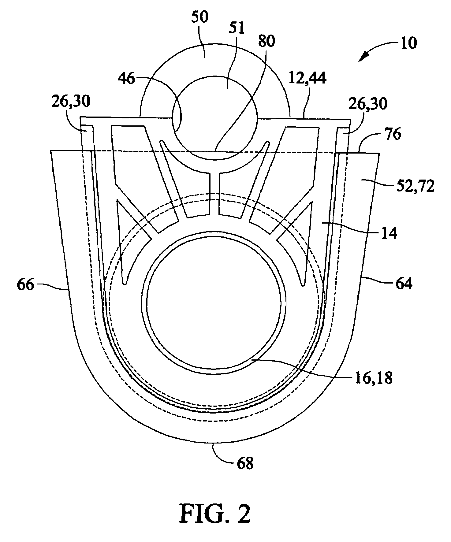
[0065]The present invention 10 comprises a first insertion portion 12 which slidably fits within a housing portion 52 in order to couple two pipes having pressurized contents in a sealed manner. Unlike prior art devices, the present art 10 easily couples and separates yet provides an assured seal between two or more pressurized pipes in a form which may be economically manufactured.

[0066]The housing portion 52 comprises a front side 56, a rear side 72, a right side 66, and a ...


PUM


Abstract

A slip fit quick disconnect pipe coupler having an insertion portion and a housing portion which mate to form a sealed coupling between pipes. The insertion portion and housing portion are separable to decouple the pipes.

Description

[0001]This application claims priority of U.S. Provisional Patent Applications #60 / 683,233, filed May 20, 2005, entitled Slip Fit Quick Disconnect Pipe Coupler and #60 / 763,043 filed Jan. 27, 2006, entitled Slip Fit Quick Disconnect Pipe Decoupling Tool.BACKGROUND OF THE INVENTION[0002]The art of the present invention relates to pipe couplers in general and more particularly to an improved slip fitting pipe coupler having a housing and insertion portion which is capable of inline coupling of pressurized pipes and further capable of quick disconnection without the use of specialized tools. The device and method of use represents an improvement over the prior art, often known as a pitless adaptor or pipe union, by providing a unique and quick pipe coupling and decoupling which does not require the use of pipe or other types of wrenches and may be manufactured at less cost, uniquely from polymers such as the NORYL® material from General Electric Plastics. The insertion portion positivel...

Claims


Application Information

Patent Timeline
Patent Type & Authority Patents(United States)
IPC IPC(8): F16L19/02
CPCF04D29/607F16L37/26F16L19/02
Inventor WEBER, WALTER L.
Owner WEBER PATENT HLDG
Why Eureka
Try Eureka