Vortical flow rotor
a rotor and flow technology, applied in the field of rotors, can solve the problems of higher performance motors, more expensive production, and more torque, and achieve the effects of reducing the cost of production, and increasing the cost of production
- Summary
- Abstract
- Description
- Claims
- Application Information
AI Technical Summary
Benefits of technology
Problems solved by technology
Method used
Image

Examples
first embodiment
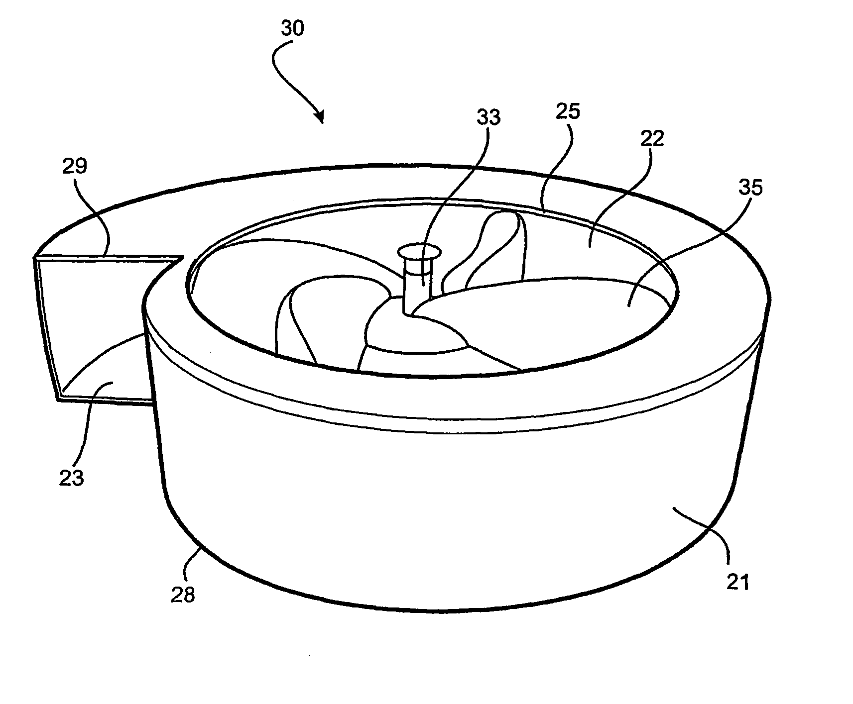
[0045]the invention, which is shown in FIGS. 5 to 7, comprises a centrifugal blower fan which can be utilized for delivery of high pressure fluid from the outlet and it is anticipated that one particular use would be as a blower which can be used in such applications as improving combustion in furnaces.
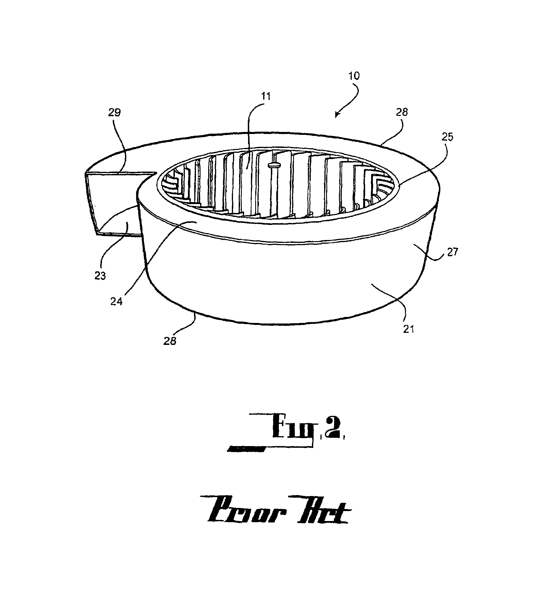
[0046]The blower fan 30 according to the first embodiment comprises a housing 21 of substantially identical form to the housing of the conventional fan 10 described above and so in the drawings, like numerals are used to depict like parts. The rotor 31 according to the embodiment again is provided with a vane supporting member 32, although this has the form of a bowl or member like a disc with the central portion pushed laterally out from the plane of the disc. The bowl 32 is driven by a central axle 33 connected to a motor.
[0047]The embodiment incorporates four vanes 35 supported by the bowl 32. Each vane is a substantially rigid member of uniform thickness and having a general tear-...
third embodiment
[0052]a rotor according to the invention is depicted in FIG. 9.
[0053]In this embodiment, the fan blades 35 are attached directly to the driving axle 33 and no supporting bowl or panel is provided. Instead the rear panel 23 is configured to substantially conform with the curve of the sides of the vanes 35 so that when assembled, there is only a small gap between the vanes and the end wall.
[0054]While in the case of a third embodiment, the general appearance is quite similar to that of many axial-flow rotors, the rotor according to a third embodiment may be distinguished from such rotors in that the configuration of the vanes causes a very different flow pattern to that of a conventional axial-flow rotor. A conventional axial flow rotor causes the fluid to flow substantially in an axial direction whereas the rotor according to the third embodiment deflects fluid flow generally outwardly toward the outer periphery of the rotor, thereby the average flow has a substantial average compone...
fifth embodiment
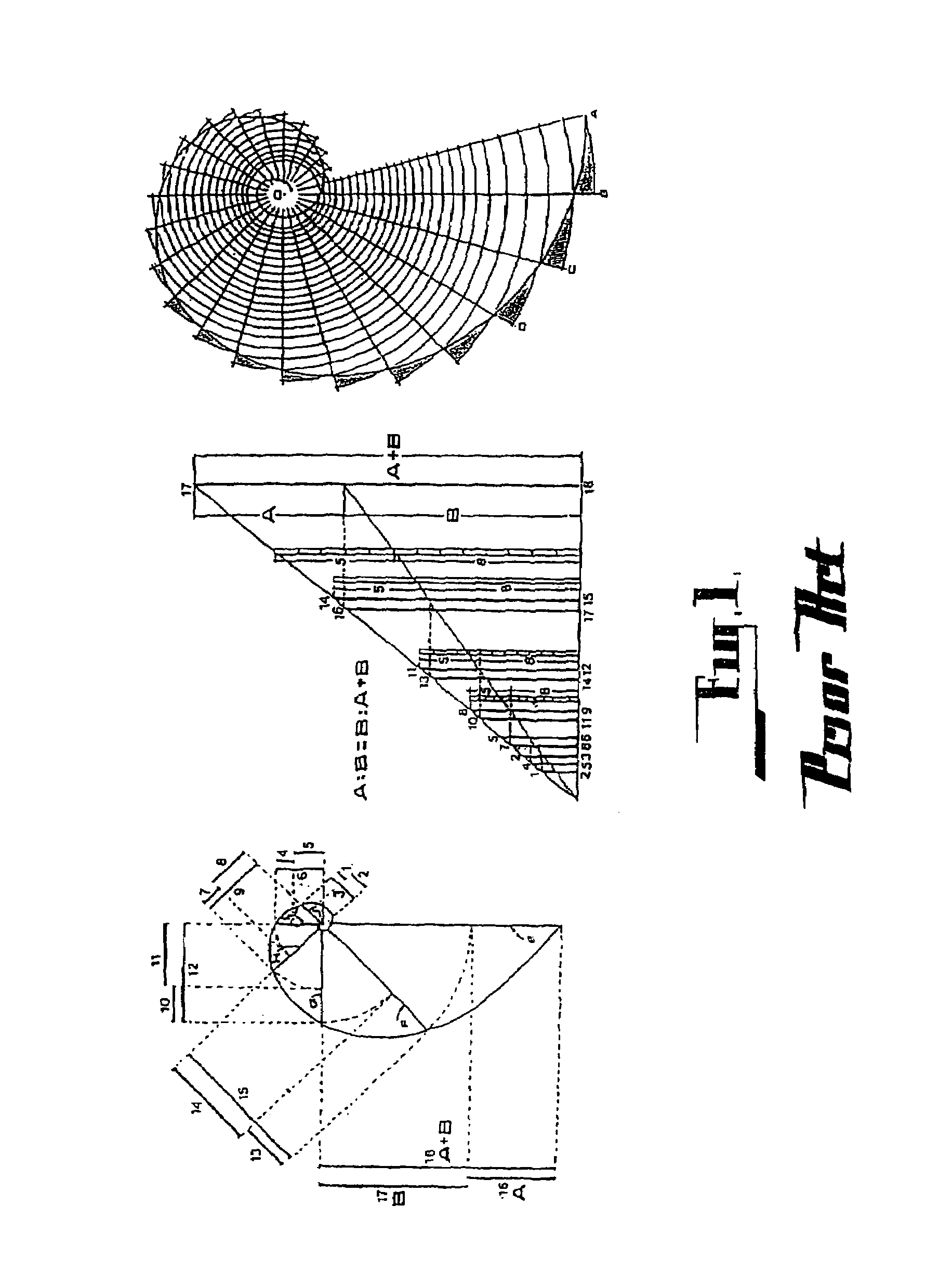
[0058]The result will be optimized if the principles disclosed by the present applicant in Patent Cooperation Treaty application number PCT / AU03 / 00004 (WO 03 / 056228 A1) are applied to the design of the fan housing. That is, if the housing is configured such that a significant portion of the inner surfaces of the housing have a curvature corresponding to that of a logarithmic spiral conforming to the Golden Section. In doing so, interference to vortical flow will be minimized, thereby further reducing turbulence and noise and increasing efficiency. In addition it has been found that the cross-sectional area of the fluid-flow path should preferably be designed to decrease or increase at a rate conforming to the Golden Ratio. a centrifugal fan designed according to the above mentioned principles is depicted in FIGS. 11 to 13. It may be noted that the embodiment comprises a housing 51 with a configuration which is substantially similar to that of a seashell or a snail. Further, it can b...
PUM
 Abstract
Description
Claims
Application Information
 - R&D
- Intellectual Property
- Life Sciences
- Materials
- Tech Scout
- Unparalleled Data Quality
- Higher Quality Content
- 60% Fewer Hallucinations
Browse by: Latest US Patents, China's latest patents, Technical Efficacy Thesaurus, Application Domain, Technology Topic, Popular Technical Reports.
© 2025 PatSnap. All rights reserved.Legal|Privacy policy|Modern Slavery Act Transparency Statement|Sitemap|About US| Contact US: help@patsnap.com