Polymerizable liquid crystal composition

a technology of liquid crystal composition and polymerizable compound, which is applied in the direction of thin material processing, transportation and packaging, chemistry apparatus and processes, etc., can solve the problems of composition insufficient adhesion property and insufficient functions of only one kind of polymerizable compound, and achieve uniform homeotropic alignment property, good coating property, and excellent stability

Active Publication Date: 2009-02-10
JNC CORP +1
View PDF12 Cites 12 Cited by
  • Summary
  • Abstract
  • Description
  • Claims
  • Application Information

AI Technical Summary

Benefits of technology

[0234]Upon preparing the solution of the polymerizable liquid crystal composition, the compounds (1) to (5) may be used after dissolving with a solvent. The solvent is selected from such solvents that have a capability of dissolving the compounds (1) to (5) and do not impair the stability and uniformity of the homeotropic alignment of the polymerizable liquid crystal composition, which is an advantage of the invention. Examples of the solvent include those solvents that have been described for preparation of the solution of the polymerizable liquid crystal composition. The using amount thereof may be set within such a range that the stability of the polymerizable liquid crystal composition is not impaired.
[0235]Upon coating the solution of the polymerizable liquid crystal composition of the invention, the solvent is removed after coating to form a polymerizable liquid crystal layer having a uniform thickness, i.e., a layer of the polymerizable liquid crystal composition, on the supporting substrate. The conditions for removing the solvent are not particularly limited, and the coated film is dried to such an extent that the solvent has been substantially removed, and the coated film of the polymerizable liquid crystal composition loses flowability. The solvent can be removed by air drying at room temperature, drying with a hot plate, drying in a drying furnace, blowing warm air or hot air. The polymerizable liquid crystal composition in the coated film may complete a nematic alignment during the drying operation of the coated film in some cases, depending on the kinds and the compositional ratios of the compounds used in the polymerizable liquid crystal composition. Accordingly, the coated film after completing the drying step can be subjected to a polymerizing step without subjecting to a heat-treating step described later. For further uniformizing the alignment of the liquid crystal molecules in the coated film, the coated film after the drying step may be subjected to a heat treatment and then to photopolymerization.
[0236]Preferred ranges of the temperature and time for the heat treatment of the coated film, the wavelength of light used for light irradiation, and the amount of light radiated from a light source vary depending on the kinds and compositional ratios of the compounds used in the polymerizable liquid crystal composition, and the presence or absence and the addition amount of the photopolymerization initiator. Accordingly, the conditions of the temperature and time for the heat treatment of the coated film, the wavelength of light used for light irradiation, and the amount of light radiated from a light source described later are considered to be approximative ranges.
[0237]The heat treatment of the coated film is preferably carried out under such conditions that the solvent is removed, and a uniform alignment of the polymerizable liquid crystal is obtained. The heat treatment may be carried out at a temperature higher than the liquid crystal phase transition temperature of the polymerizable liquid crystal composition. One example of the heat-treating method is a method of heating the coated film to a temperature where the polymerizable liquid crystal composition exhibits a nematic liquid crystal phase, whereby the polymerizable liquid crystal composition in the coated film forms a nematic alignment. A nematic alignment may be formed by changing the temperature of the coated film within a temperature range where the polymerizable liquid crystal composition exhibits a nematic liquid crystal phase. In this method, the coated film is heated to a high temperature region within the aforementioned temperature range to complete substantially a nematic alignment of the coated film, and then the temperature is decreased to make an alignment with higher regularity. In both cases using the heat-treating methods, the heat-treating temperature may be from room temperature to 120° C., preferably room temperature to 100° C., more preferably from room temperature to 90° C., and further preferably from room temperature to 70° C. The heat-treating time is generally from 5 seconds to 2 hours, preferably from 10 seconds to 40 minutes, and more preferably from 20 seconds to 20 minutes. In order to increase the temperature of the layer containing the polymerizable liquid crystal composition to the prescribed temperature, the heat-treating time is preferably 5 seconds or more. In order to prevent the productivity from being deteriorated, the heat-treating time is preferably 2 hours or less. The cooling time of the coated film is also important for providing a uniform homeotropic alignment, and is generally from 5 seconds to 20 minutes, preferably from 5 seconds to 10 minutes, and more preferably from 5 seconds to 5 minutes, at room temperature. The polymerizable liquid crystal layer of the invention is thus completed in this manner.
[0238]The nematic alignment state of the polymerizable liquid crystal compounds formed in the polymerizable liquid crystal layer is fixed by polymerizing the polymerizable liquid crystal composition through irradiation of light. The wavelength of the light used for the light irradiation is not particularly limited, and an electron beam, an ultraviolet ray, a visible ray, an infrared ray (heat ray) and the like may be used. In general, an ultraviolet ray or a visible ray is used. The range of the wavelength is generally from 150 to 500 nm, preferably from 250 to 450 nm, and more preferably from 300 to 400 nm. Examples of the light source include a low pressure mercury lamp (such as a bactericidal lamp, a fluorescent chemical lamp and a black light), a high pressure discharge lamp (such as a high pressure mercury lamp and a metal halide lamp), and a short arc discharge lamp (such as a super high pressure mercury lamp, a xenon lamp and a mercury xenon lamp). Preferred examples of the light source include a metal halide lamp, a xenon lamp, a super high pressure mercury lamp and a high pressure mercury lamp. The wavelength range of the light source used for irradiation may be selected by inserting a filter between the light source and the polymerizable liquid crystal layer to pass the specific wavelength range. The amount of light radiated from the light source is generally from 2 to 5,000 mJ / cm2, preferably from 10 to 3,000 mJ / cm2, and more preferably from 100 to 2,000 mJ / cm2. The temperature condition upon irradiation of light is preferably set similarly to the heat-treating temperature.
[0239]The atmosphere upon polymerization may be any of a nitrogen atmosphere, an inert gas atmosphere and an air atmosphere, and for ensuring the adhesion property to the supporting substrate, it is preferred that the polymerization is firstly carried out in an air atmosphere and then carried out in a nitrogen atmosphere or an inert gas atmosphere. According to the procedure, the epoxy component firstly undergoes polymerization to exhibit adhesion property. The acrylate component is then polymerized to improve the strength of the coated film. In alternative, the oxygen concentration may be appropriately controlled, whereby radical polymerization is suppressed, and simultaneously cationic polymerization is carried out.

Problems solved by technology

However, sufficient functions may not be obtained from only one kind of a polymerizable compound.
However, the composition may suffer increase of the viscosity of the solution to provide a problem in storage stability, and thus it is necessary to mix an additive immediately before use.
However, the composition is still insufficient in adhesion property and has room for improvements.

Method used


Image

  • Polymerizable liquid crystal composition
  • Polymerizable liquid crystal composition
  • Polymerizable liquid crystal composition

Examples


example 1

Preparation of Polymerizable Liquid Crystal Composition (1)

[0283]

Compound (1-1-3)51% by weightCompound (2-3)17% by weightCompound (3-1-1) 5% by weightCompound (4-1A-1)13% by weightCompound (4-3-2)14% by weight

[0284]The composition MIX 1 having the aforementioned formulation was prepared. A weight ratio of 0.02 of a polymerization initiator, IRGACURE 907 (produced by Ciba Specialty Chemicals Co., Ltd.) and a weight ratio of 0.02 of a polymerization initiator, CPI-110P (produced by SAN-APRO Ltd.) were added to MIX 1. Cyclohexanone was further added to the composition to provide a polymerizable liquid crystal composition (1) having a solvent content of 70% by weight.

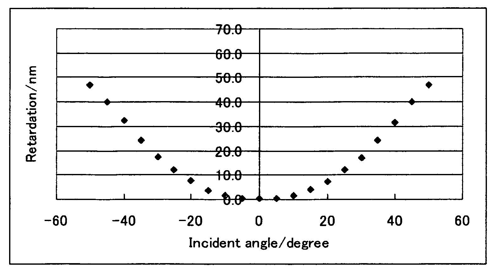
[0285]Polyamic acid (Lixon Aligner PIA-5310, produced by Chisso Corp.) was coated on a glass substrate (S-1112, produced by Matsunami Glass Industries, Ltd.), and after drying at 80° C. for 3 minutes, baked at 210° C. for 30 minutes. The polymerizable liquid crystal composition (1) was coated on the glass substrate having p...

example 2

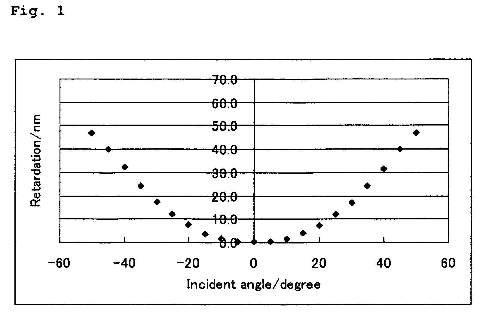
[0286]A polymerizable liquid crystal composition (2) was prepared in the same manner as in Example 1 except that the compound (3-1-1) was changed to the compound (3-2-2), and a liquid crystal film was obtained from the polymerizable liquid crystal composition (2) in the same manner as in Example 1. The liquid crystal film exhibited a uniform homeotropic alignment. The measurement of retardation of the film provided results that were similar to the results shown in FIG. 1. The evaluation of adhesion property of the liquid crystal film to the supporting substrate was A. The solution was good in storage stability with no change in viscosity confirmed.

example 3

[0287]A polymerizable liquid crystal composition (3) was prepared in the same manner as in Example 1 except that the compound (3-1-1) was changed to the compound (3-3-1), and a liquid crystal film was obtained from the polymerizable liquid crystal composition (3) in the same manner as in Example 1. The liquid crystal film exhibited a uniform homeotropic alignment. The measurement of retardation of the film provided results that were similar to the results shown in FIG. 1. The evaluation of adhesion property of the liquid crystal film to the supporting substrate was A. The solution was good in storage stability with no change in viscosity confirmed.


PUM

PropertyMeasurementUnit
tilt angleaaaaaaaaaa

Abstract

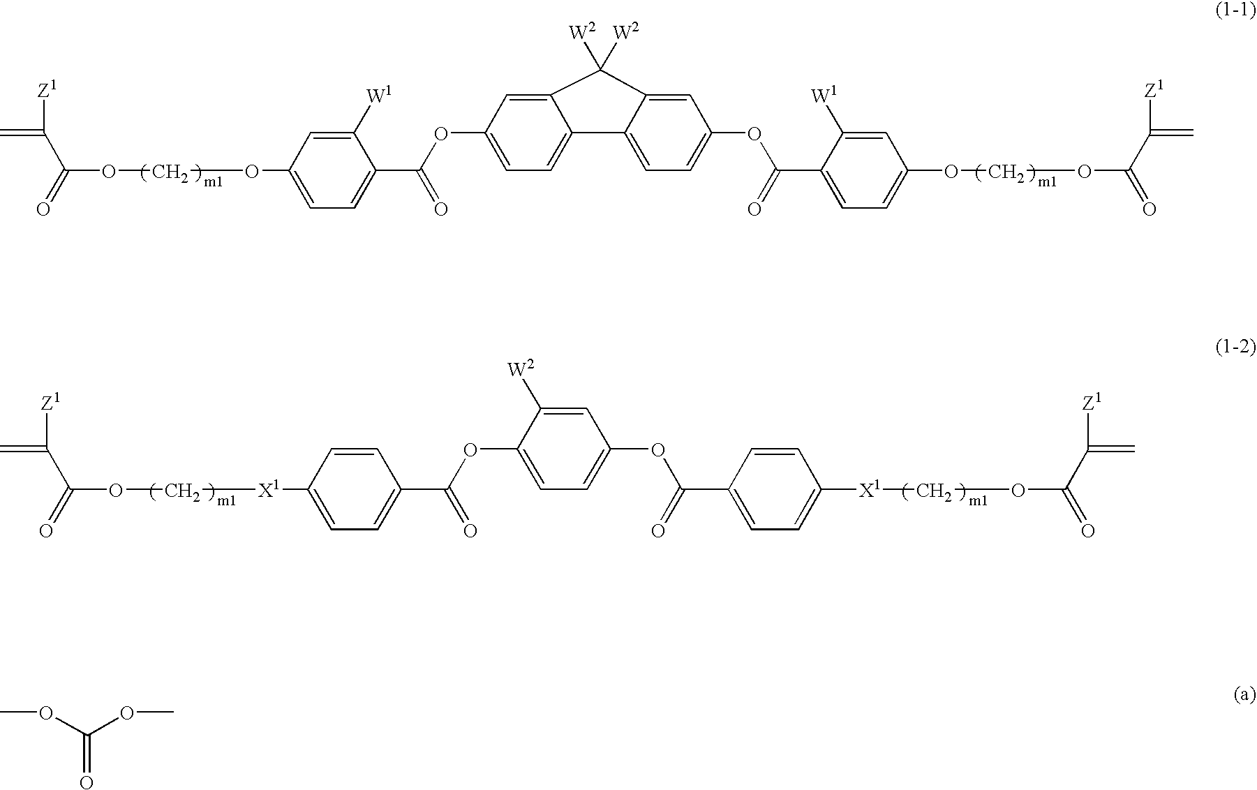
Such a polymerizable liquid crystal composition is to be provided that is excellent in stability in a solution state, shows good coating property on a supporting substrate, and has a uniform homeotropic alignment property. The polymerizable liquid crystal composition contains an acrylate compound, an epoxy compound and a bisphenol fluorene compound. The polymerizable liquid crystal composition contains a compound selected from a group of compounds represented by formulae (1-1) and (1-2) as a component (A), a compound selected from a group of compounds represented by formula (2) as a component (B), a compound selected from a group of compounds represented by formulae (3-1) to (3-3) as a component (C) and a compound selected from a group of compounds represented by formulae (4-1A), (4-1B), (4-2), (4-3), (4-4) and (4-5) as a component (D), and may optionally contain a compound selected from a group of compounds represented by formulae (5-1) and (5-2) as a component (E). The bisphenol fluorene compound is effective for controlling a uniform homeotropic alignment of the polymerizable liquid crystal composition.

Description

FIELD OF THE INVENTION[0001]The present invention relates to a polymerizable liquid crystal composition, which may be used as a liquid crystal film by coating on a supporting substrate. The invention also relates to an optical compensation film, an optical device and a liquid crystal display device using the liquid crystal film.BACKGROUND OF THE INVENTION[0002]A polymerizable compound having a liquid crystal phase provides a polymer having such a function as optical compensation through polymerization. This is because the alignment of the liquid crystal molecules is fixed by polymerization. In order to utilize the function of the polymer, various kinds of polymerizable compounds have been developed. However, sufficient functions may not be obtained from only one kind of a polymerizable compound. Accordingly, there have been such attempts that a composition is prepared by using plural polymerizable compounds, and the composition is polymerized (as described in JP-A-10-319408 (GB 2324...

Claims


Application Information

Patent Timeline
Patent Type & Authority Patents(United States)
IPC IPC(8): C09K19/32C09K19/12C09K19/30
CPCC09K19/2007C09K19/32C09K19/3861C09K19/42C08F220/30C08F220/36C09K19/28Y10T428/1005C09K2019/0444C09K2019/0448C08F2220/305C08F2220/365Y10T428/1041Y10T428/1095Y10T428/10Y10T428/1036C08F220/301C08F220/305C08F220/365C09K2323/00C09K2323/02C09K2323/03C09K2323/031C09K2323/061
Inventor HIRAI, YOSHIHARU
Owner JNC CORP
Why Eureka
Try Eureka