Rope or cable retainer

a technology of rope or cable, which is applied in the direction of ropes and cables for vehicles/pulleys, garments, applications, etc., can solve the problems of not providing a device for loosening or tightening the tension member, and difficulty in tying the rop

Inactive Publication Date: 2009-02-17
HILLIER CLYDE
View PDF4 Cites 6 Cited by
  • Summary
  • Abstract
  • Description
  • Claims
  • Application Information

AI Technical Summary

Problems solved by technology

Occasionally, as during inclement weather, it may be difficult to tie the rope as described.
When the depressing force is released, a shearing force is applied to the linear tension member from the axial misalignment, which frictionally secures the tension member within the device.
In addition to being unable to accommodate tension members of differing diameters, the known prior art has not provided a device for loosening or tightening a tension member using only access to an intermediate portion of the tension member.

Method used


Image

  • Rope or cable retainer
  • Rope or cable retainer
  • Rope or cable retainer

Examples


Embodiment Construction

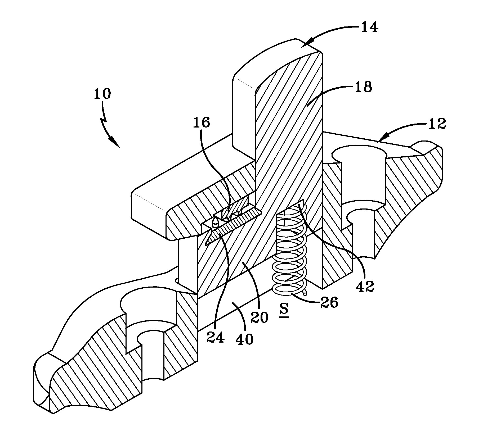
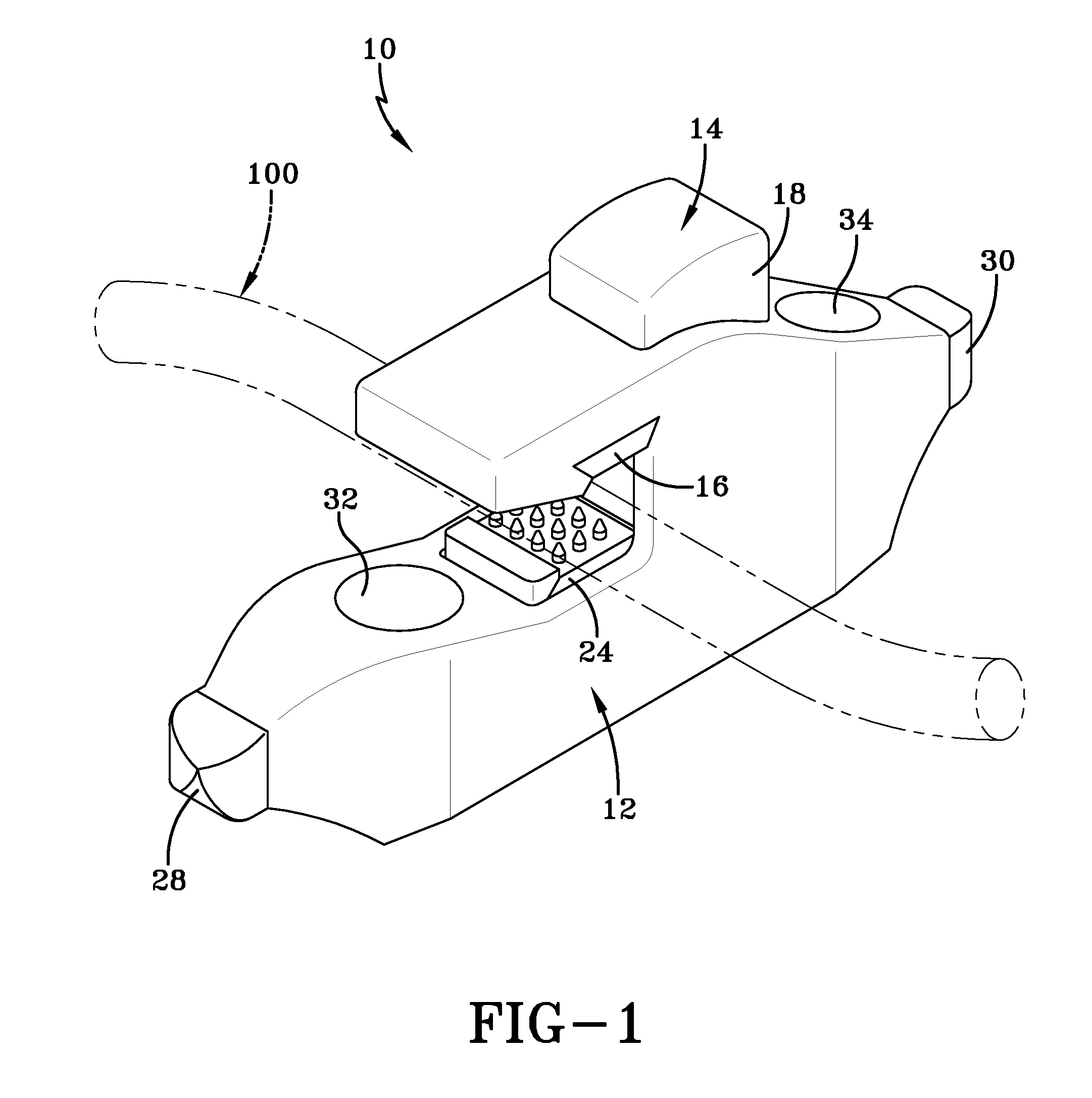
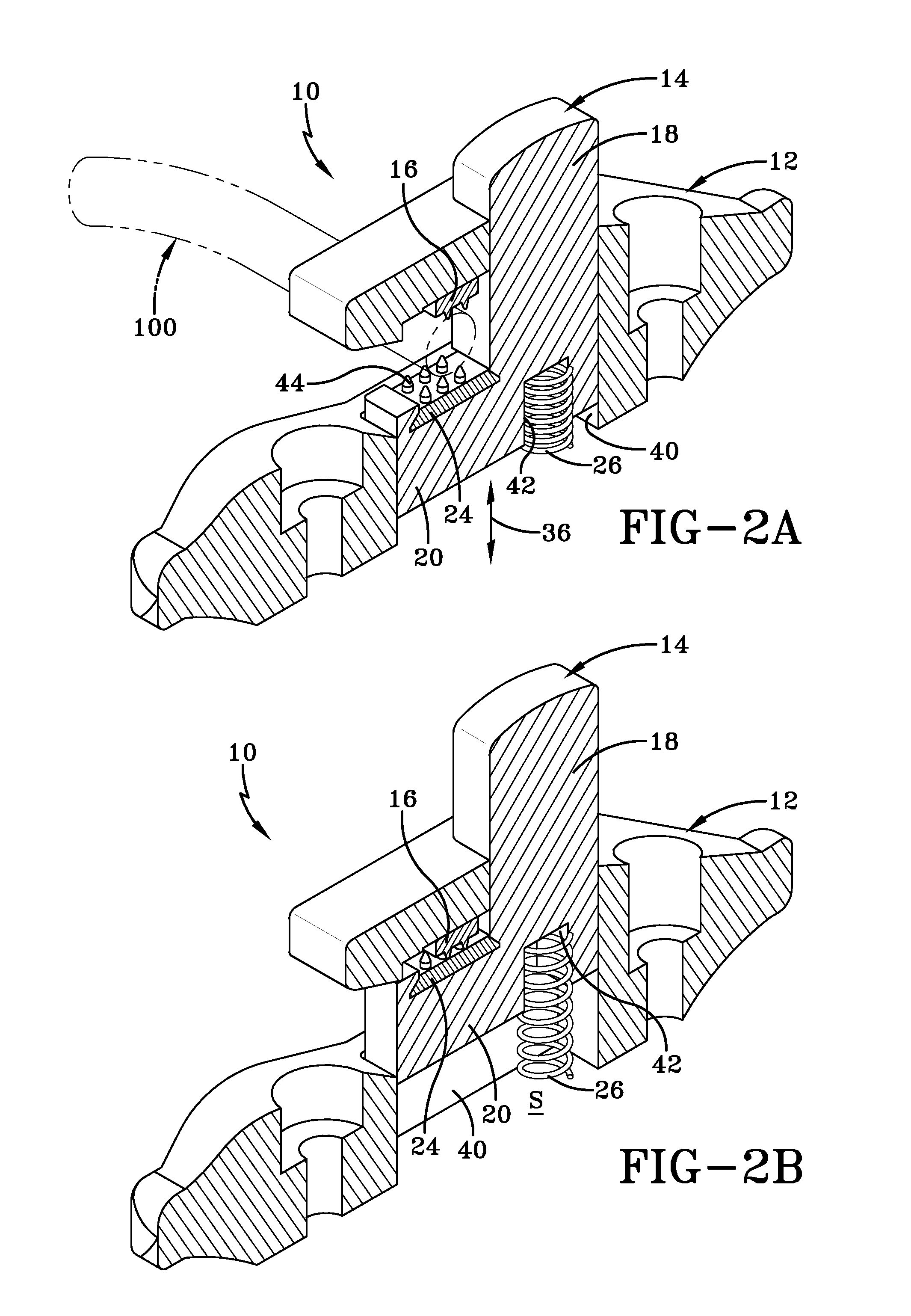
[0016]Referring first to FIG. 1, a retaining device 10 is shown perspective view. The device releasably retains a rope, cable or other linear tension member 100, shown in phantom lining, in relation to a surface to which the device is mounted. The device 10 has a body 12 and a plunger 14 that are movable relative to each other. The plunger 14 is positioned within a shaped internal cavity (not shown in FIG. 1) of the body 12. The body 12 has a first surface 16 disposed on it. This first surface 16 frictionally engages the tension member 100, which is also frictionally engaged by a second surface 24, the second surface being disposed on the plunger 14. As will be seen, the plunger 14 is mounted in the body 12, with a portion 18 extending upwardly through the top of the body, so that vertical movement of the plunger effects movement of the second surface 24, but the first and second surfaces 16, 24 remain in substantially parallel relationship.

[0017]The illustrated embodiment of the bo...


PUM


Abstract

A rope, cable or other linear tension member is retained along its length by a device 10 having a body 12 with a plunger 18 that is movably located in an internal cavity 14 of the body. The body provides a first surface 16 to engage the tension member and the plunger provides a second surface 24 that is disposed in substantially parallel relationship to the first surface. A biasing means 26 is used to urge the plunger upwardly in the internal cavity, so that the first and second surfaces are urged towards registration. Opposing ends 28, 30 of the body may be shaped in a manner to provide a cleat upon which the tension member may be wound or tied off. Mounting means 32, 34 in the body permit the body to be fixed to a surface.

Description

CROSS-REFERENCE TO RELATED APPLICATIONS[0001]This application claims no benefit of priority.TECHNICAL FIELD[0002]The embodiments disclosed herein relate to a device for retaining a rope, cable, or similar linear tension member. More particularly, the device provides the capacity to receive such a rope or cable along a length thereof, without requiring access to an end of the linear tension member.BACKGROUND OF THE ART[0003]For purposes of this application, the term “linear tension member,” which may also be referred to as the “tension member,” is used to identify the workpiece with which applications of the device will be found. The linear tension member will be understood to encompass ropes, cables, chains and other equivalents. A variety of linear tension members are commonly used, especially in nautical applications, such as to secure a nautical vessel to a dock or similar support structure. Securing such vessels to a dock, for instance, typically requires that knots be tied in t...

Claims


Application Information

Patent Timeline
Patent Type & Authority Patents(United States)
IPC IPC(8): F16G11/00F16B2/12
CPCB63B21/08F16G11/10Y10T24/3969Y10T24/44581F16G11/101
Inventor HILLIER, CLYDE
Owner HILLIER CLYDE
Why Eureka
Try Eureka