Endocardial lead cutting apparatus

a cutting apparatus and endocardial lead technology, applied in the field of endocardial lead cutting apparatus, can solve the problems of increasing electrode resistance, unable to cut, and endocardial leads that are not used in the heart and venous path,

Active Publication Date: 2010-01-26
SPECTRANETICS
View PDF4 Cites 86 Cited by
  • Summary
  • Abstract
  • Description
  • Claims
  • Application Information

AI Technical Summary

Problems solved by technology

Although the state of the art in implemented pulse generator or pacemaker technology and endocardial lead technology has advanced considerably, endocardial leads nevertheless occasionally fail, due to a variety of reasons, including breakage of a lead, insulation breaks, breakage of the inner helical coil conductor and an increase in electrode resistance.
Although it obviously would be desirable to easily remove such unused leads, in the past surgeons usually have avoided attempts to remove inoperative leads because the risk of removing them exceeded the risk of leaving them in.
The risks of leaving unused myocardial leads in the heart and venous path include increased likelihood that an old lead may facilitate infection, which in turn may necessitate removal of the lead to prevent continued bacteremia and abcess formation.
Furthermore, there is an increased likelihood of the formation of blood clots in the atrial chamber about entangled leads.
Such clots may embolize to the lung and produce severe complications and even fatality.
Furthermore, the presence of unused leads in the venous pathway and inside the heart can cause considerable difficulty in the positioning and attachment of new endocardial leads in the heart.
Even then, it is possible that a clot has formed so the removal of the leads causes various sized emboli to pass to the lungs, producing severe complications.
In cases where the lead tip has become attached by scar tissue to the myocardial wall, removal of the lead always has presented major problems and risks.
Sufficient traction on such leads in a removal attempt could cause disruption of the myocardial wall prior to release of the embedded lead tip.
The tines or flanges of other types of leads that are not tightly scarred to the myocardial wall present similar risks.
Continual strong pulling or twisting of the outer free end of the lead could cause rupture of the atrial wall or the ventricular wall if there is such tight circumferential encasement of adherent channel scar tissue in the venous path.
The risks of removing the lead by such traction and rotation of the lead are so high that, if it becomes imperative that the lead be removed (as in the case of infection), most surgeons have elected to open the patient's chest and surgically remove the lead rather than attempt removal by applying traction and rotation thereto.

Method used


Image

  • Endocardial lead cutting apparatus
  • Endocardial lead cutting apparatus
  • Endocardial lead cutting apparatus

Examples


Embodiment Construction

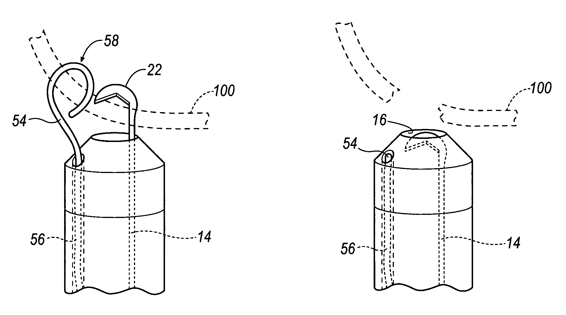
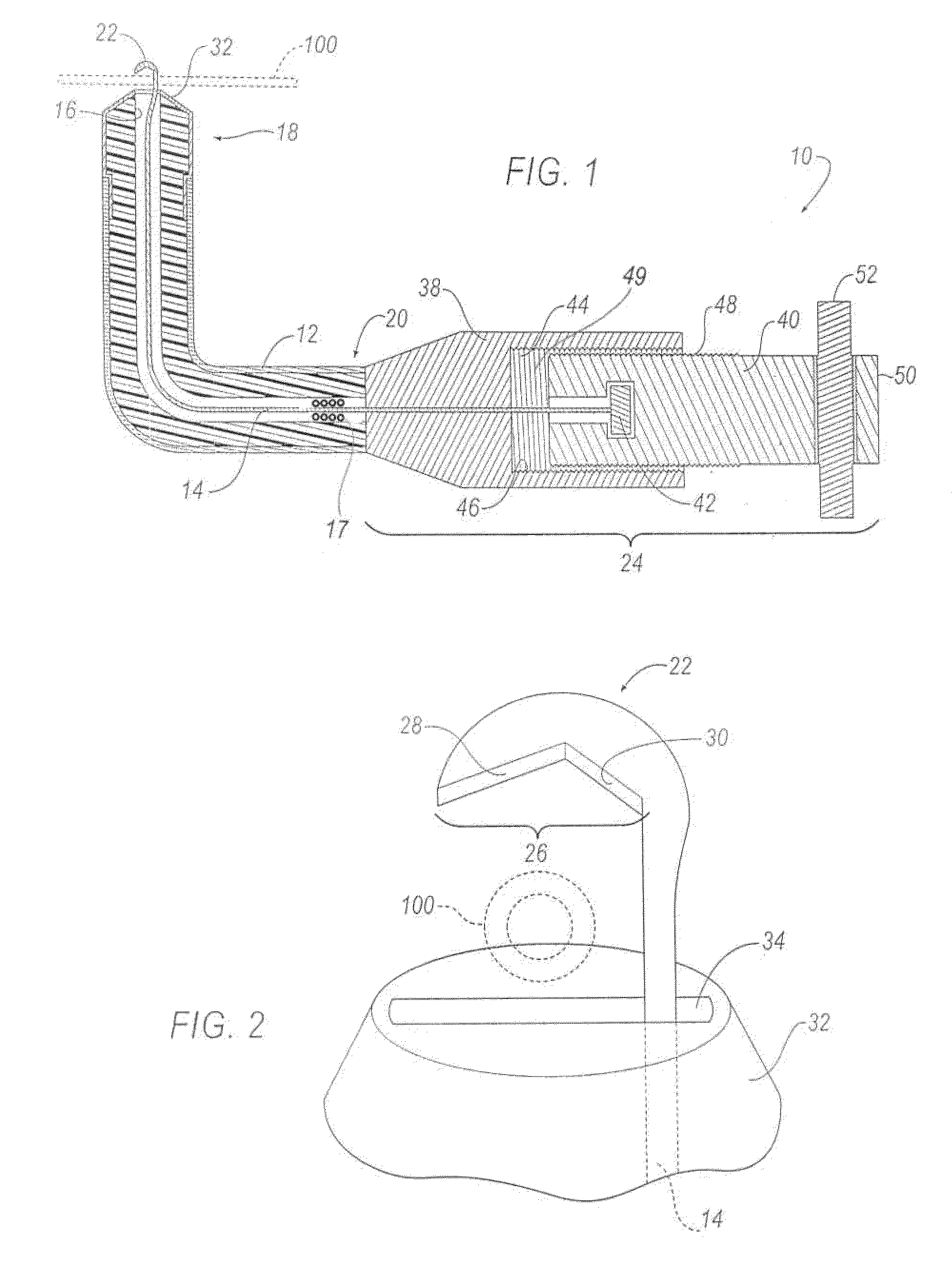
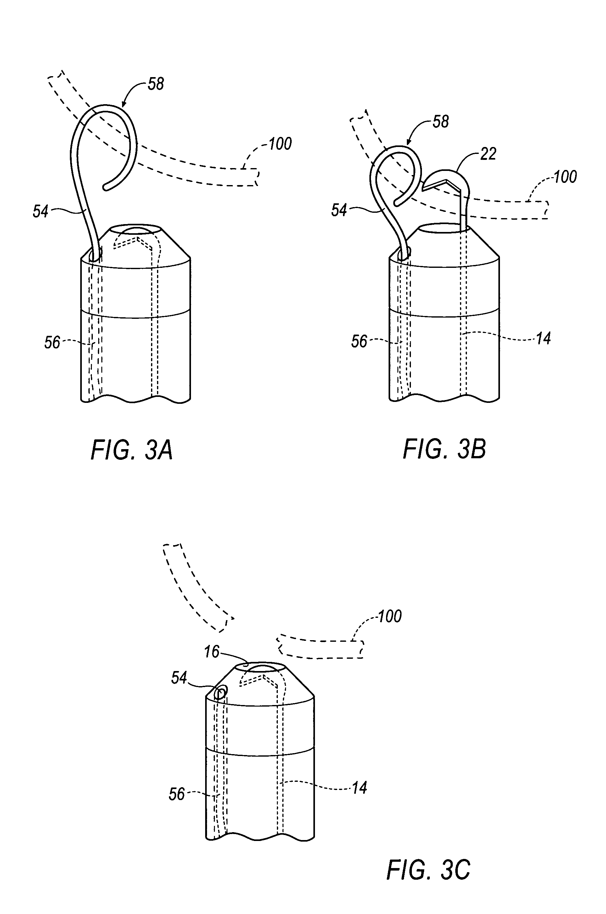
[0017]Referring generally to FIGS. 1-3, embodiments of an endocardial lead cutting apparatus are generally referred to at 10.

[0018]Referring to FIG. 1, the apparatus 10 includes a tubular member 12. The tubular member 12 is generally flexible and preferably made from a polymer material. Additionally, the tubular member 12 is made from a generally radiopaque material such that the material does not allow the passage of x-rays or other forms of radiation. The tubular member 12 may include reinforcements such as a braid or compressed coil (not shown) to strengthen the tubular member 12 and resist compression during operation.

[0019]The apparatus 10 includes a tension member 14 disposed within the tubular member 12. The tension member 14 is received within a first channel 16 of the tubular member 12 and includes a distal end 18 and a proximal end 20. The tension member 14 is generally flexible and moveable between an extended position and a retracted position. Further, the first channel ...


PUM


Abstract

The invention provides an apparatus for cutting an endocardial lead within a patient. The apparatus includes a tubular member and a tension member disposed therein. The tension member includes a distal end and a proximal end. A blade is affixed to the distal end of the tension member and an adjustment mechanism is adapted to adjust the tension member and blade between an extended position and a retracted position. The adjustment mechanism includes a female member, a male member and an anchor. The anchor is affixed to the proximal end of the tension member and the male member. Insertion and withdrawal of the male member within the female member moves the tension member and the blade between the extended position and the retracted position. An alternate embodiment includes a capture mechanism or guide wire for drawing the apparatus and lead closer together before extending the blade and cutting the lead.

Description

FIELD OF THE INVENTION[0001]This invention relates generally to an endocardial lead cutting apparatus and, more particularly, to an apparatus including at least one blade movable between an extended position and a retracted position for cutting endocardial leads from within a patient's body.BACKGROUND OF THE INVENTION[0002]In the past, various types of endocardial leads and electrodes have been introduced into different chambers of a patient's heart, including the right ventricle, right atrial appendage, and atrium as well as the coronary sinus. These flexible leads usually are composed of an insulator sleeve that contains an implanted helical coil conductor that is attached to an electrode tip. This electrode is placed in contact with myocardial tissue by passage through a venous access, often the subclavian vein or one of its tributaries, which leads to the endocardial surface of the heart chambers. The tip with the electrode contact is held in place by trabeculations of myocardia...

Claims


Application Information

Patent Timeline
Patent Type & Authority Patents(United States)
IPC IPC(8): A61B17/32
CPCA61B17/320016A61N1/056A61B17/22031A61B17/32056A61B17/32075A61B2017/2212A61B2017/2217
Inventor COE, MICHAEL S.SELLERS, DUNCAN
Owner SPECTRANETICS
Why Eureka
Try Eureka