Pressure sensor having improved arrangement of sensor chip for minimizing influence of external vibrations

a pressure sensor and chip technology, applied in the field of pressure sensors, can solve the problems of sensing error of the pressure sensor and the pressure sensor b, and achieve the effect of minimizing the influence of vibration on the pressure-receiving surface and high accuracy of the pressure sensor

Inactive Publication Date: 2009-02-17
DENSO CORP
View PDF13 Cites 2 Cited by
  • Summary
  • Abstract
  • Description
  • Claims
  • Application Information

AI Technical Summary

Benefits of technology

[0012]With the above arrangement, since the pressure-receiving surface of the sensor chip is accordingly to be parallel to the direction of the vibrations, the influence of the vibrations on the pressure-receiving surface can be minimized. Consequently, high accuracy of the pressure sensor can be ensured.

Problems solved by technology

Consequently, even when there is no change in the actual value of a pressure of the environment, the value of the pressure sensed by the pressure sensor 30 may change, thus resulting in a sensing error of the pressure sensor 30.
In this case, however, since the pressure-receiving surface 10a of the sensor chip 10 is perpendicular to the direction of vibrations caused by opening and closing operation of the door 40, the vibrations may result in a sensing error of the pressure sensor 30.

Method used


Image

  • Pressure sensor having improved arrangement of sensor chip for minimizing influence of external vibrations
  • Pressure sensor having improved arrangement of sensor chip for minimizing influence of external vibrations
  • Pressure sensor having improved arrangement of sensor chip for minimizing influence of external vibrations

Examples


first embodiment

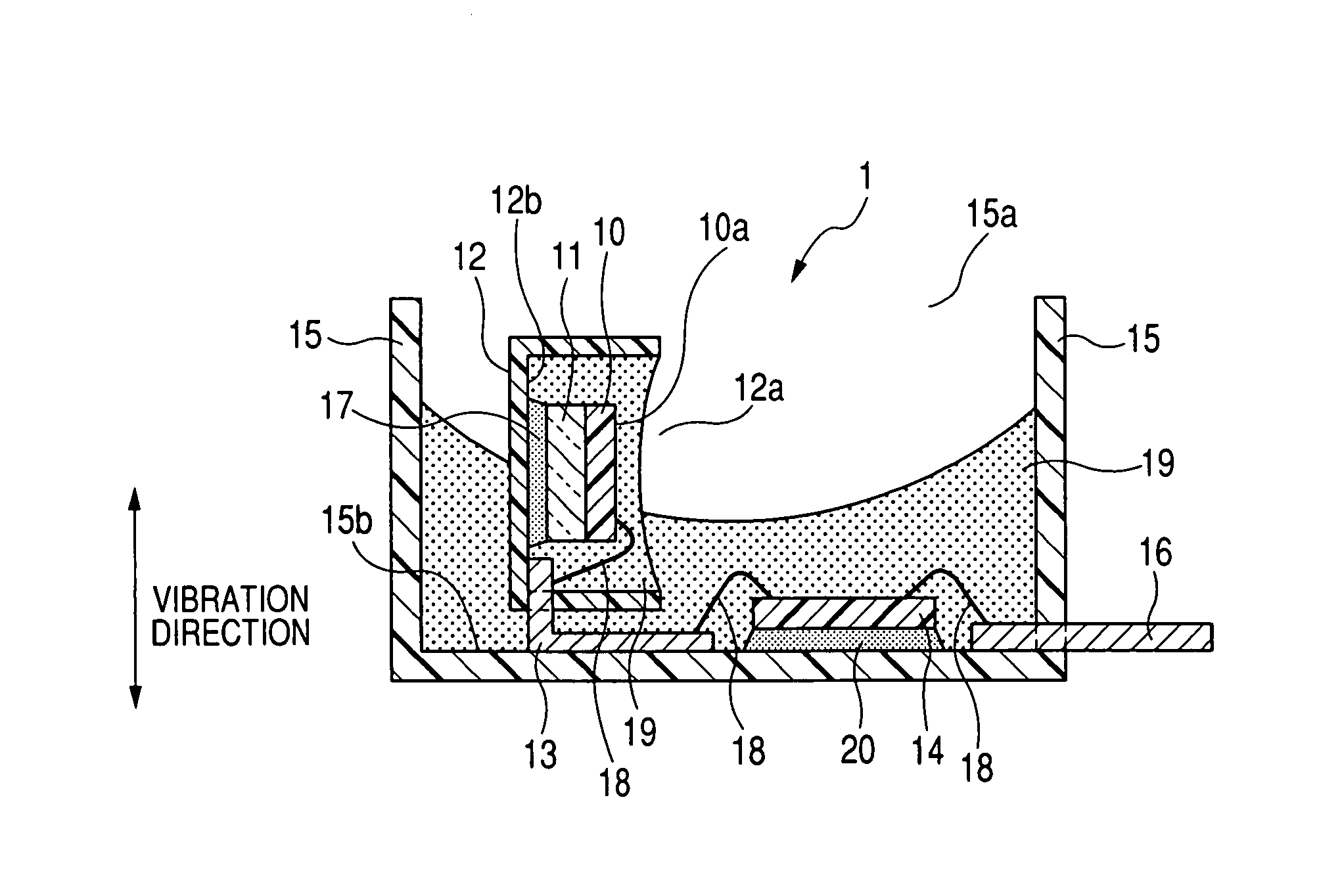
[0026]FIG. 1 shows the overall structure of a pressure sensor 1 according to the first embodiment of the invention. The pressure sensor 1 is designed to be installed in an interior space formed in a door of a vehicle to sense the air pressure change in the interior space caused by a collision against the door.

[0027]The interior space may be formed between an outer panel on the outside and a door trim on the inner side of the door. Otherwise, when there is further provided an inner trim between the outer panel and the door trim, the interior space may formed either between the outer panel and the inner trim or between the inner trim and the door trim.

[0028]As shown in FIG. 1, the pressure sensor 1 includes a sensor chip 10, a glass seat 11, a sub case 12, a plurality of terminals 13, a circuit chip 14, a main case 15, and a plurality of terminals 16.

[0029]The sensor chip 10 includes a diaphragm (not shown) for sensing pressure. The diaphragm has a bridge circuit formed therein and a ...

second embodiment

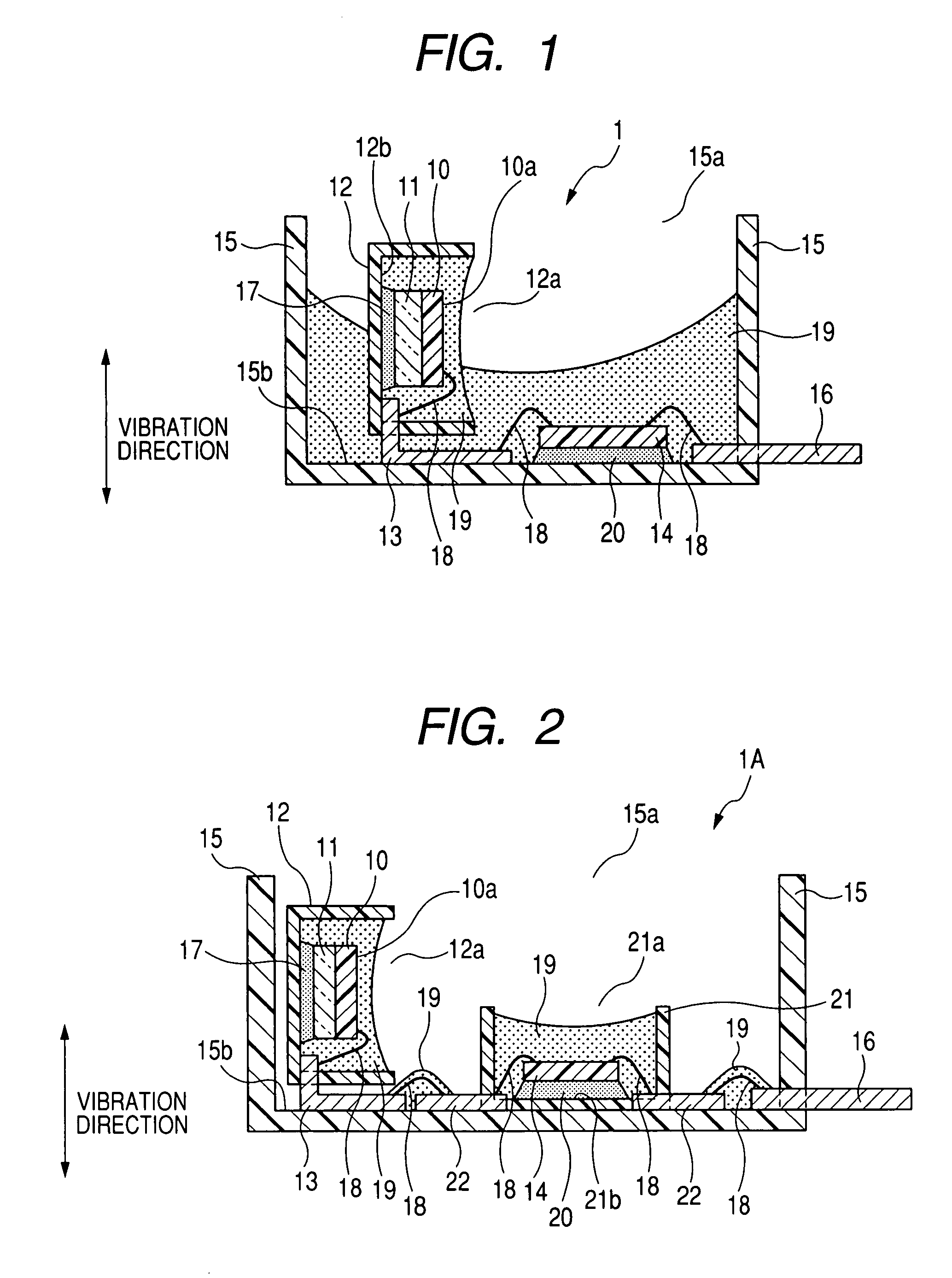
[0045]FIG. 2 shows the overall structure of a pressure sensor 1A according to the second embodiment of the invention. The structure of the pressure sensor 1A is similar to that of the pressure sensor 1 according to the first embodiment; accordingly, only the differences therebetween will be described.

[0046]In the pressure sensor 1, as described previously, the circuit chip 14 is directly mounted to the main case 15.

[0047]In comparison, as shown in FIG. 2, the pressure sensor 1A further includes a sub case 21 and a plurality of terminals 22.

[0048]The sub case 21 is made of resin and has the shape of a cup with an opening 21a and an inner end surface 21b. The sub case 21 is disposed on the inner end surface 15b of the main case 15 so that the inner end surface 21b of the sub case 21 is parallel to the inner end surface 15b of the main case 15. The circuit chip 14 is received in the sub case 21 and fixed to the inner end surface 21b by the adhesive 20.

[0049]The terminals 22 are provide...

third embodiment

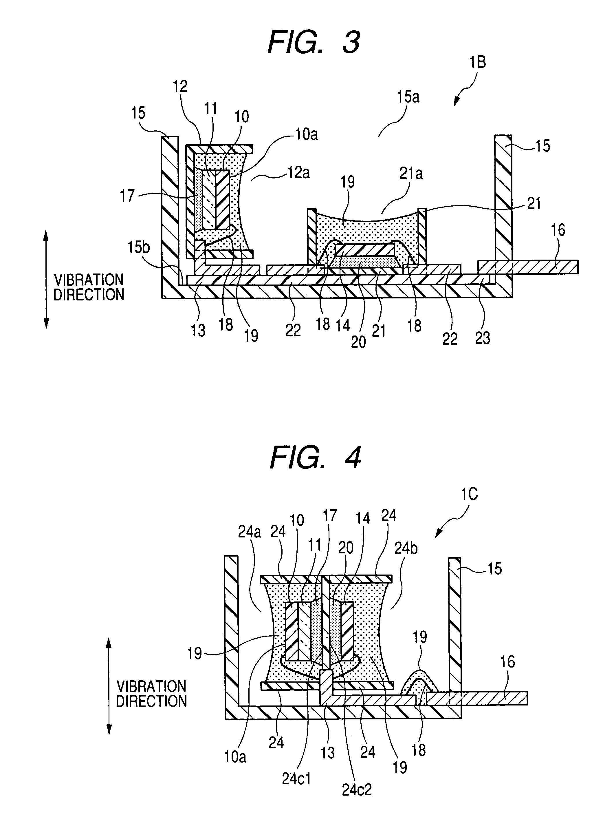
[0053]FIG. 3 shows the overall structure of a pressure sensor 1B according to the third embodiment of the invention. The structure of the pressure sensor 1B is similar to that of the pressure sensor 1A according to the second embodiment; accordingly, only the differences therebetween will be described.

[0054]In the pressure sensor 1A, as described previously, the terminals 22 are electrically connected to the terminals 13 or 16 by the wire bonding 18.

[0055]In comparison, as shown in FIG. 3, the pressure sensor 1B further includes a printed wiring board 23 that electrically connects the terminals 22 to the terminals 13 or 16.

[0056]The printed wiring board 23 is made up of a glass epoxy board or flexible board, on which a conductive pattern (not shown) is formed by wiring patterns and contact pads. The printed wiring board 23 is fixed to the inner end surface 15b of the main case 15 by screws (not shown) or an adhesive (not shown). The terminals 13, 22, and 16 are joined to the corresp...


PUM

PropertyMeasurementUnit
pressureaaaaaaaaaa
conductiveaaaaaaaaaa
stressaaaaaaaaaa

Abstract

A pressure sensor, which is to be used in an environment involving vibrations, includes a case and a sensor chip. The case has an inner surface that is to be disposed perpendicular to a direction of the vibrations. The sensor chip is to sense a pressure in the environment and generate a sensing signal representative of the sensed pressure. The sensor chip has a pressure-receiving surface and is secured in the case with the pressure-receiving surface perpendicular to the inner surface of the case. With such an arrangement, since the pressure-receiving surface of the sensor chip is accordingly to be parallel to the direction of the vibrations, the influence of the vibrations on the pressure-receiving surface can be minimized. Consequently, high accuracy of the pressure sensor can be ensured.

Description

CROSS-REFERENCE TO RELATED APPLICATION[0001]This application is based on and claims priority from Japanese Patent Application No. 2006-296354, filed on Oct. 31, 2006, the content of which is hereby incorporated by reference in its entirety into this application.BACKGROUND OF THE INVENTION[0002]1. Technical Field of the Invention[0003]The present invention relates generally to pressure sensors including a sensor chip for sensing pressure. More particularly, the invention relates to a pressure sensor that has an improved arrangement of sensor chip for minimizing the influence of external vibrations on the pressure sensor.[0004]2. Description of the Related Art[0005]Conventionally, pressure sensors, which include a sensor chip for sensing pressure, generally further include a case, a circuit chip, and a protective gel. The case has an inner end surface, on which the sensor and circuit chips are mounted, and an opening through which the protective gel is filled in the case to protect th...

Claims


Application Information

Patent Timeline
Patent Type & Authority Patents(United States)
IPC IPC(8): G01L7/08
CPCG01L19/02G01L19/0627H01L2224/48091H01L2224/48137H01L2224/73265H01L2924/19107H01L2924/00014
Inventor MURATA, TAKESHI
Owner DENSO CORP
Why Eureka
Try Eureka