Femoral prosthesis

Inactive Publication Date: 2009-02-17
STRYKER EURO OPERATIONS HLDG LLC
View PDF14 Cites 38 Cited by
  • Summary
  • Abstract
  • Description
  • Claims
  • Application Information

AI Technical Summary

Benefits of technology

[0018]The prosthesis can also include a projecting feature which can act to prevent subsidence of the stem

Problems solved by technology

With known sleeves it is difficult for the surgeon to judge the required tapering thickness of such a sleeve so that maximum support

Method used


Image

  • Femoral prosthesis
  • Femoral prosthesis
  • Femoral prosthesis

Examples


Embodiment Construction

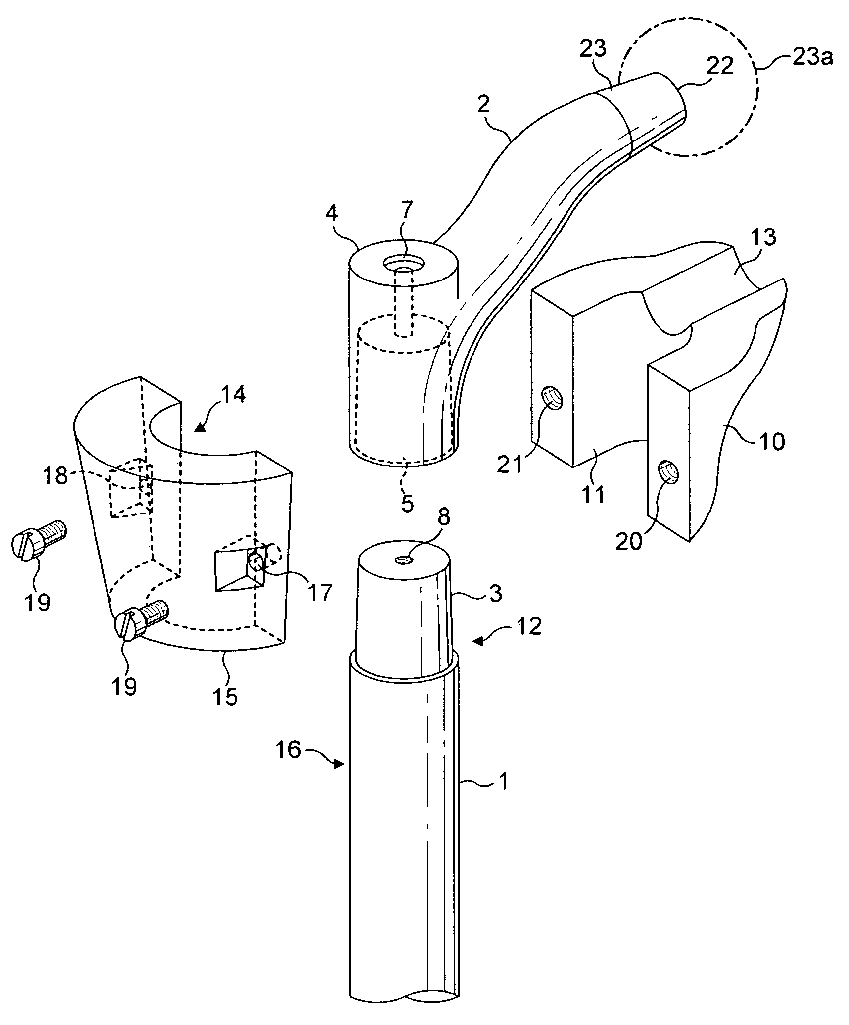
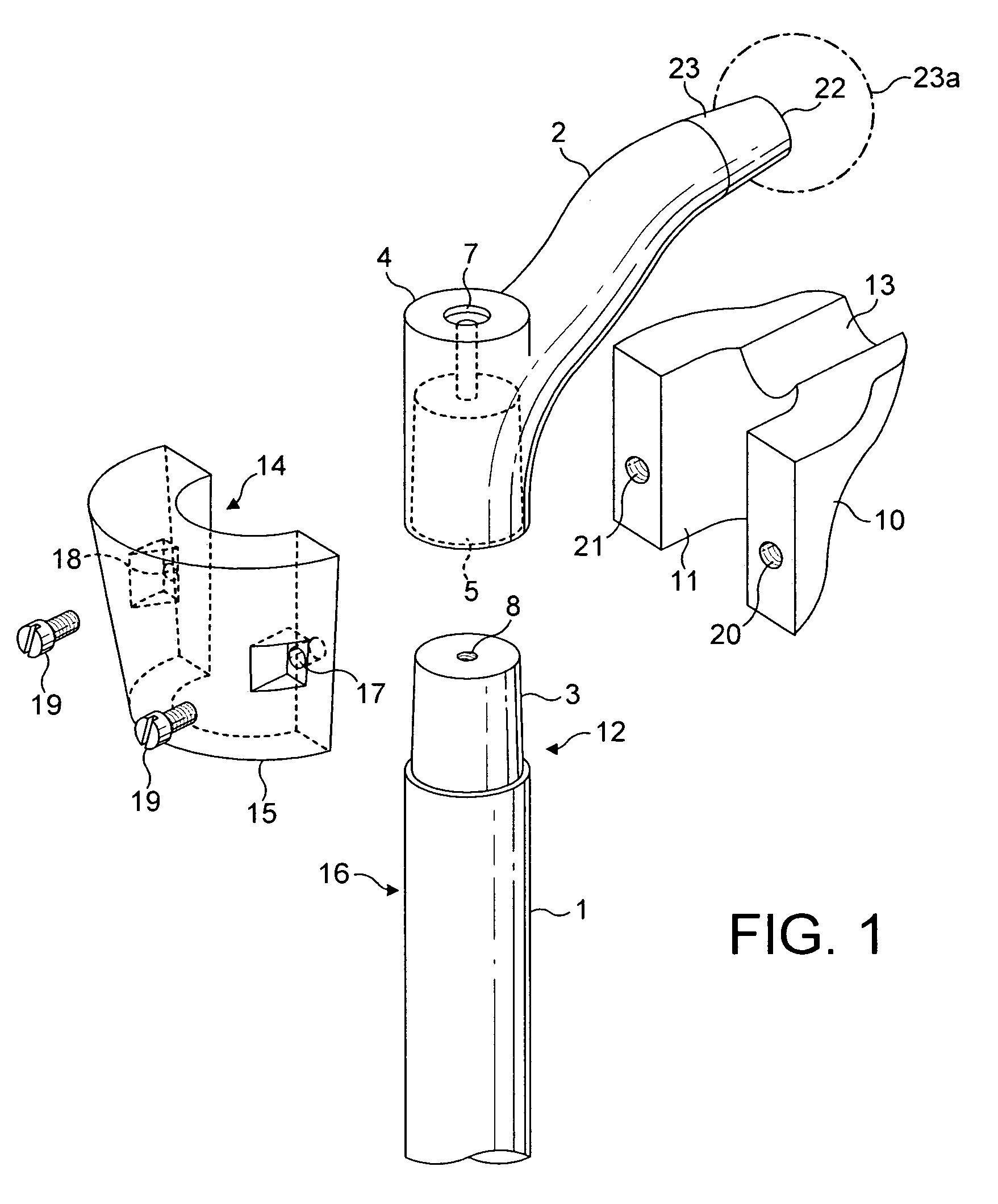
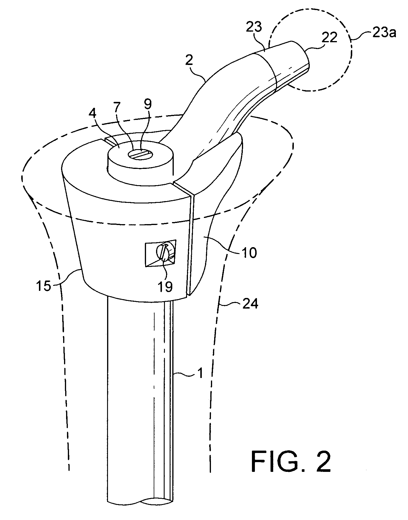
[0035]As shown in FIGS. 1 and 2 of the drawings a femoral prosthesis according to a preferred embodiment of the present invention comprises a stem 1 having a shoulder and / or neck portion 2. The proximal end of stem 1 has a tapered spigot or trunnion 3 and neck portion 2 has a raised boss 4 which provides a shoulder. Located within boss 4 is a tapered socket 5 which is shaped and dimensioned to locate on tapered spigot 3 of stem 1. A screw 9 (shown in FIG. 2) is provided which can extend through a flanged opening 7 in boss 4 and into a screw threaded opening 8 in spigot 3 to hold shoulder and / or neck portion 2 rigidly in position on stem 1. This stem 1 can be of any convenient and well known shape for use in a bone canal.

[0036]Included in the construction is a medial proximal sleeve component 10 which has a groove 11 which is shaped to cooperate with medial side 12 of stem 1 and neck portion 2. Sleeve component 10 also has a trough 13 to adapt it to the distal side of stem portion 2....


PUM


Abstract

A femoral prosthesis including a stem for insertion in a femoral canal and a shoulder and/or neck portion characterized by a proximal sleeve having an outer circumferential wall and comprising two or more proximal sleeve components, each of which provides part of the circumferential outer surface of the sleeve, and means for securing the proximal sleeve components in position at the proximal end of the stem.

Description

BACKGROUND OF THE INVENTION[0001]This invention relates to a femoral prosthesis which is for insertion into the bone canal of a femur and is particularly, although not exclusively, applicable for use in revision surgery.[0002]When carrying out revision surgery it is usually necessary to provide rigid support of the proximal end of the bone canal due to this end of the canal tending to be flared out when the previous prosthesis was removed. It is known to provide a filling in this area and it is also known to provide a proximal sleeve on the prosthesis to accommodate the lack of bone.[0003]With known sleeves it is difficult for the surgeon to judge the required tapering thickness of such a sleeve so that maximum support is obtained and, in any case, it is usually necessary for the sleeve to be attached to the stem of the prosthesis prior to assembly.[0004]The present invention is intended to overcome some of the difficulties referred to above by providing a sleeve which can be fitted...

Claims


Application Information

Patent Timeline
IPC IPC(8): A61F2/32A61B17/82A61F2/00A61F2/28A61F2/30A61F2/36A61F2/46
CPCA61F2/30734A61F2/30739A61F2/367A61B17/82A61F2/30767A61F2/4684A61F2002/30131A61F2002/30332A61F2002/30344A61F2002/30433A61F2002/30434A61F2002/30604A61F2002/30616A61F2002/3069A61F2002/30729A61F2002/30738A61F2002/30785A61F2002/30794A61F2002/30797A61F2002/30808A61F2002/30975A61F2002/3611A61F2002/3625A61F2002/365A61F2002/3652A61F2220/0033A61F2220/0041A61F2230/0013A61F2002/30339A61F2002/3079
Inventor PICHONCUEILLE, CHRISTOPHEDELOGE, NICOLAS
Owner STRYKER EURO OPERATIONS HLDG LLC
Why Eureka
Try Eureka