Hydrodynamic bearing assembly

a technology of bearing assembly and hydrodynamic type, which is applied in the direction of bearings, shafts and bearings, rotary bearings, etc., can solve the problems of reducing the working life of the bearing assembly, lubricant leakage from the bearing assembly, and increasing the abrasion between the bearing surface and the sha

Inactive Publication Date: 2009-02-24
HON HAI PRECISION IND CO LTD
View PDF24 Cites 3 Cited by
  • Summary
  • Abstract
  • Description
  • Claims
  • Application Information

AI Technical Summary

Benefits of technology

[0005]In operation of the bearing assembly, the rotating shaft generates a counterforce on the surrounding lubricant which supports the shaft whilst it rotates in the bearing hole. The counterforce presses the lubricant to move toward open ends of the bearing assembly along the hydrodynamic pressure generating grooves. This causes lubricant leakage from the bearing assembly. The leakage of the lubricant from the bearing assembly results in a failure of generation of the hydrodynamic pressure and an increase in abrasion between the bearing surface and the shaft, thus reducing the working life of the bearing assembly.

Problems solved by technology

This causes lubricant leakage from the bearing assembly.
The leakage of the lubricant from the bearing assembly results in a failure of generation of the hydrodynamic pressure and an increase in abrasion between the bearing surface and the shaft, thus reducing the working life of the bearing assembly.

Method used


Image

  • Hydrodynamic bearing assembly
  • Hydrodynamic bearing assembly
  • Hydrodynamic bearing assembly

Examples


Embodiment Construction

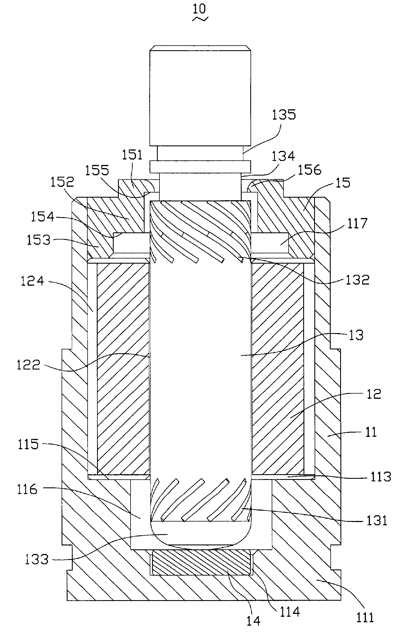
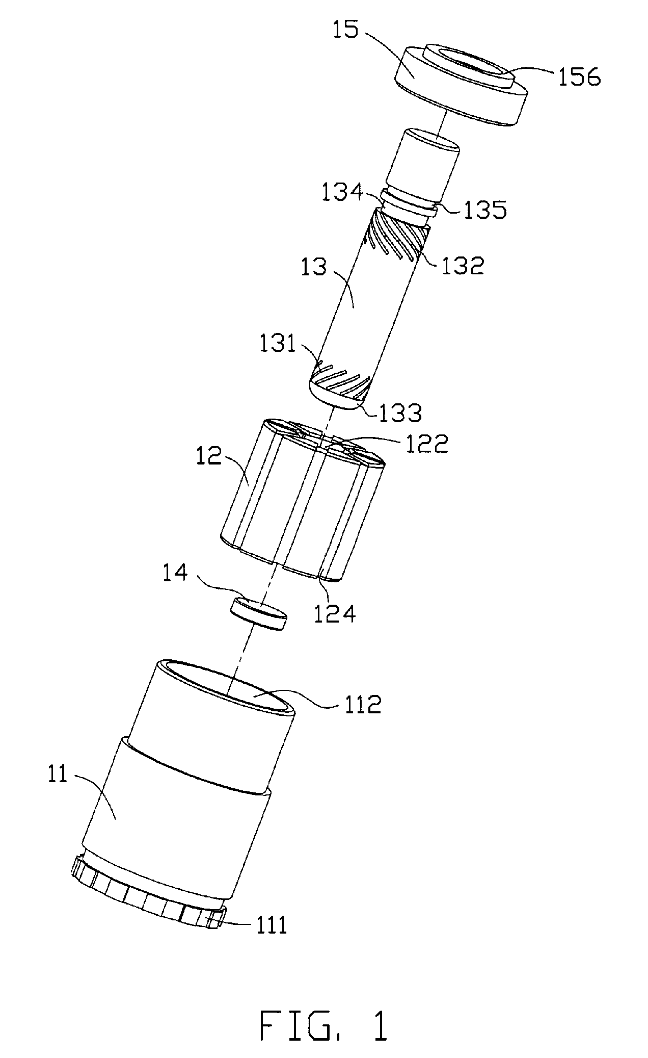
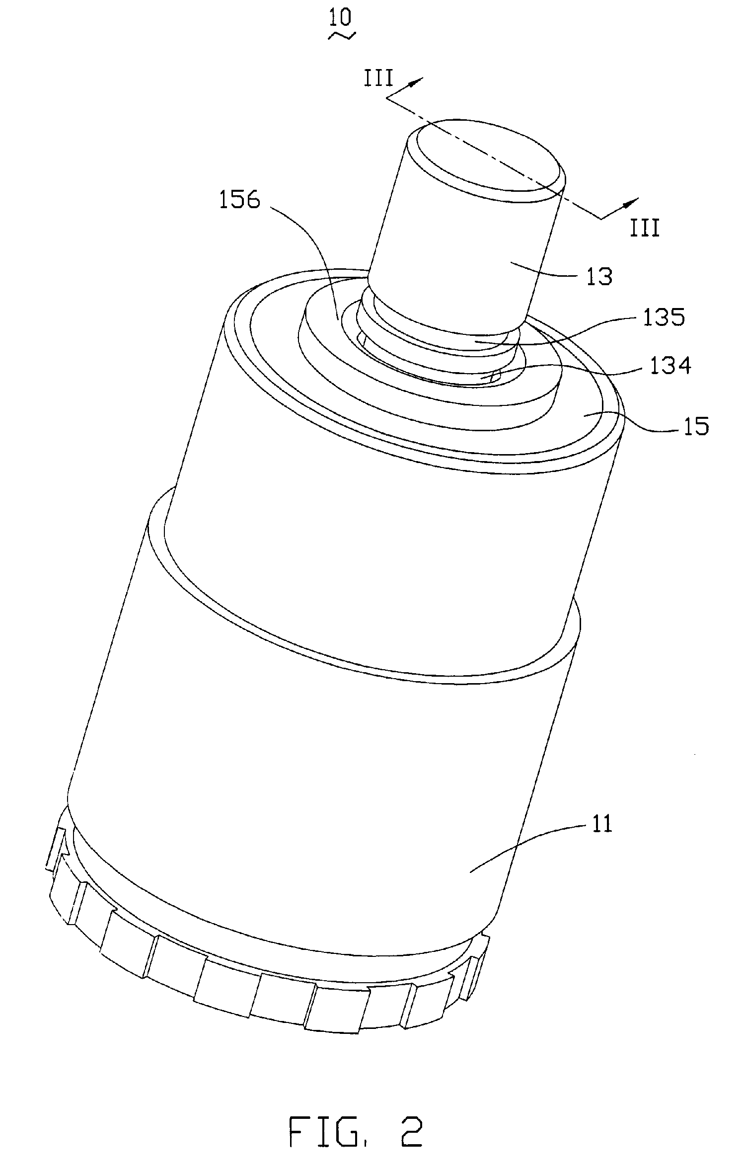
[0012]Referring to FIGS. 1 through 3, a hydrodynamic bearing assembly 10 according to a preferred embodiment of the present invention is shown. The bearing assembly 10 includes a bearing sleeve 11, a ceramic bearing 12 disposed in the bearing sleeve 11, a shaft 13 rotatably received in a bearing hole 122 of the bearing 12, a thrust washer 14 abutting against a bottom distal end of the shaft 13, a sealing cover 15 disposed at a top portion of the shaft 13, and lubricant (not shown) filled in spaces formed between an inner surface of the bearing 12 and an outer surface of the shaft 13.

[0013]Particularly referring to FIG. 3, the bearing sleeve 11 has a generally U-shaped cross section with a bottom end thereof being closed, thereby defining a closed end 111 at the bottom end thereof and an open end 112 (labeled in FIG. 1) at a top end thereof. A receiving chamber 113 is defined in the bearing sleeve 11 for enclosing a variety of components therein. The thrust washer 14, the bearing 12 ...


PUM


Abstract

A hydrodynamic bearing assembly (10) includes a bearing sleeve (11) defining a receiving chamber (113) therein, a bearing (12) received in the receiving chamber of the bearing sleeve, a sealing cover (15) mounted to an open end (112) of the bearing sleeve and including an enlarged section (153) adjacent to the bearing, a shaft (13) extending through the sealing cover and rotatably disposed in the bearing, on which a plurality lubricant pressure generating grooves are defined, and a lubricant retaining space (117) defined by the enlarged section of the sealing cover, an end of the bearing and the shaft for receiving lubricant therein. One of the sealing cover and the shaft defines a groove (134) therein, while the other one of the sealing cover and the shaft extends a flange (156) into the groove.

Description

CROSS-REFERENCES TO RELATED APPLICATION[0001]This application is related co-pending to U.S. patent application Ser. No. 11 / 308,471, filed on Mar. 28, 2006, assigned to the same assignee as this application, and entitled “HYDRODYNAMIC BEARING ASSEMBLY”. The disclosure of the above-identified co-pending application is incorporated herein by reference.FIELD OF THE INVENTION[0002]The present invention relates generally to bearing assemblies, and more particularly to a bearing assembly of hydrodynamic type.DESCRIPTION OF RELATED ART[0003]Due to the ever growing demand for quiet, low-friction rotational elements with extended lifetimes, hydrodynamic bearing assemblies have become increasingly used in conventional motors such as fan motors or HDDs (Hard disk drives) motors.[0004]A typical hydrodynamic bearing assembly comprises a bearing surface which defines a bearing hole, and a shaft rotatably received in the bearing hole with a gap formed between the bearing surface of the bearing and ...

Claims


Application Information

Patent Timeline
Patent Type & Authority Patents(United States)
IPC IPC(8): F16C32/06
CPCF16C17/107F16C17/26F16C33/107F16C33/74
Inventor HONG, CHIEN-LONGHUANG, CHING-HSINGSHIH, WUN-CHANGPEI, HSIEN-SHENG
Owner HON HAI PRECISION IND CO LTD
Why Eureka
Try Eureka