Modular electronic sign and method of assigning a unique identifier to common modules of said sign

a module and electronic sign technology, applied in the field of electronic signs, display and messaging systems, can solve the problems of low data rate, minimal active host, and devoid of crystal control in each modular panel, and achieve the effect of reducing costs

Inactive Publication Date: 2009-02-24
MASKENY DONALD D +1
View PDF9 Cites 64 Cited by
  • Summary
  • Abstract
  • Description
  • Claims
  • Application Information

AI Technical Summary

Benefits of technology

[0011]EROM and RAM are included with each microcontroller and therefore each modular panel of the larger sign matrix has its own “on-board” memory and control that assists in providing solutions to the deficiencies in the prior art and providing the desired needs to the end users. In particular, our electronic sign utilizing individual modular display boards having on-board memory and control can simulate a “virtual screen” by having each panel render the entire message or animation on each modular panel in its virtual screen, but only show a particular portion of said message or animation on the particular panel for the actual display matrix based upon a panel identification number (i.e., location). This permits us to show animation and messages more quickly due to pre-loading of data and character sets into EROM. Further, because of the on-board memory, more data can be loaded and accordingly, more sophisticated animation can be displayed, but without the need to add additional complicated electronic circuitry. Still further, on-board memory allows for pre-loading of data which frees up more time for actual showing of display data (messages). Yet even further, the on-board memory permits simultaneously loading and showing. And yet even further, the on-board microcontroller and memory reduces the host function during show or display, making it a minimally active host. The on-board memory allows for collection and storage of data (frames) prior to showing. Therefore, global frame “cadences” (or sequences) can be sent out along the single serial data line to show the message, animation or graphic. The cadence or sequence is a user defined order of frame display.
[0012]Other advancements include the ability for the end user to assign a “customer defined” serial number to each modular panel at the time of panel connection to the support frame. The end user can also change the serial number at his discretion or assign new serial numbers to panels if they are replaced. Also, a novel auto-baud protocol is used to set the baud rate (bit rate) for the transmission of every packet of data. Accordingly, the sign is not hampered by the confines of a pre-determined baud rate.
[0014]A further object of the present invention is to provide for quicker loading and showing of messages through the use of on-board memory.
[0017]Yet another object of the present invention is to provide for the ability to load and show a message at the same time through a cadence control scheme that controls timing of the entire message display sign.
[0020]And another object of the present invention is to provide a display sign matrix that executes complicated pattern movement of the message or animation (such as scrolling) through the use of the modular panel on-board control and memory.
[0021]Another object of the present invention is to provide a display sign matrix having advanced features that satisfies all of the desired needs of the end user but has minimally complex circuitry that is offered to end users at a reduced cost.

Problems solved by technology

A slow data rate can be used and therefore each modular panel is devoid of any crystal control.
And yet even further, the on-board microcontroller and memory reduces the host function during show or display, making it a minimally active host.

Method used


Image

  • Modular electronic sign and method of assigning a unique identifier to common modules of said sign
  • Modular electronic sign and method of assigning a unique identifier to common modules of said sign
  • Modular electronic sign and method of assigning a unique identifier to common modules of said sign

Examples


Embodiment Construction

, contained herein below, may be better understood when accompanied by a brief description of the drawings, wherein:

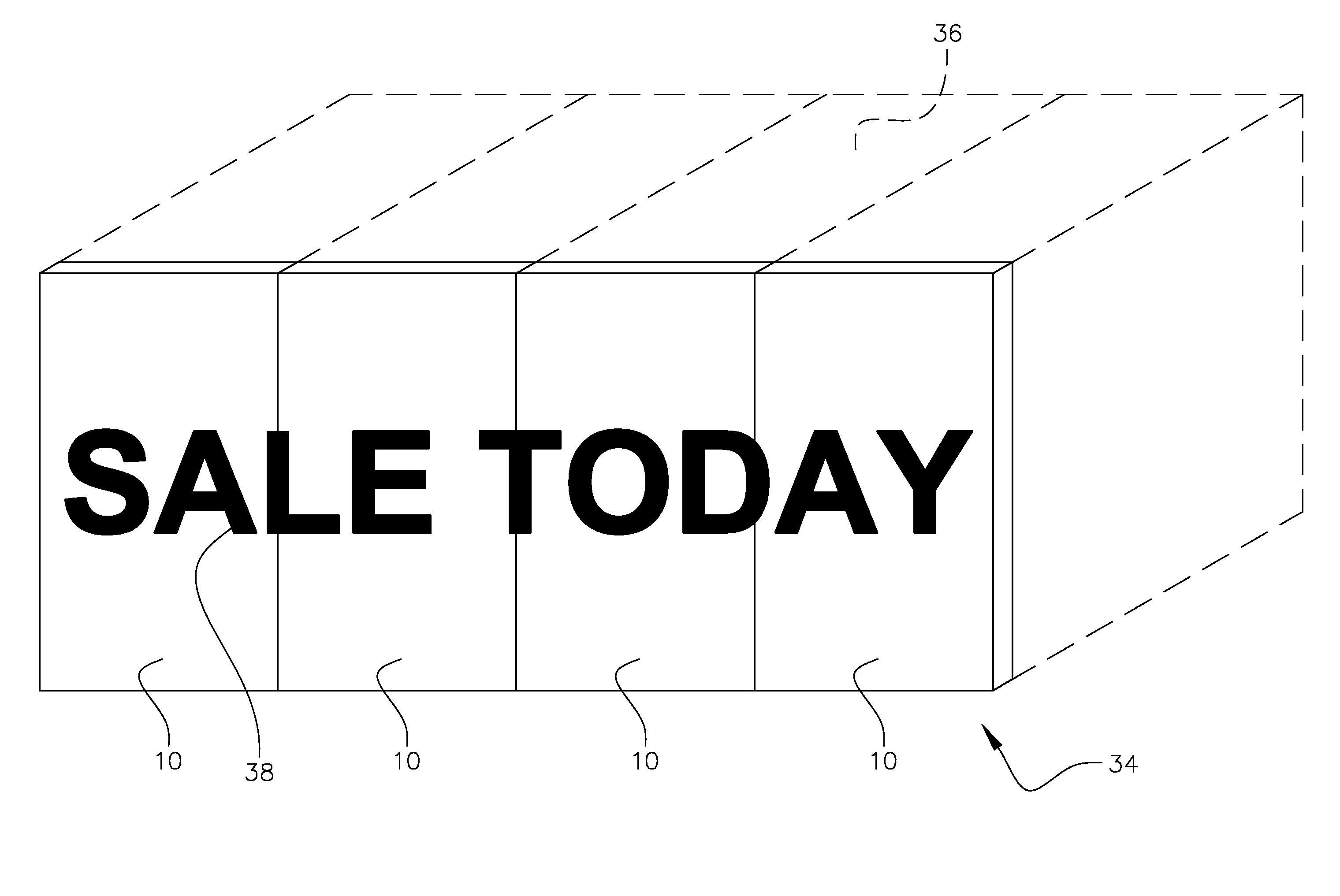
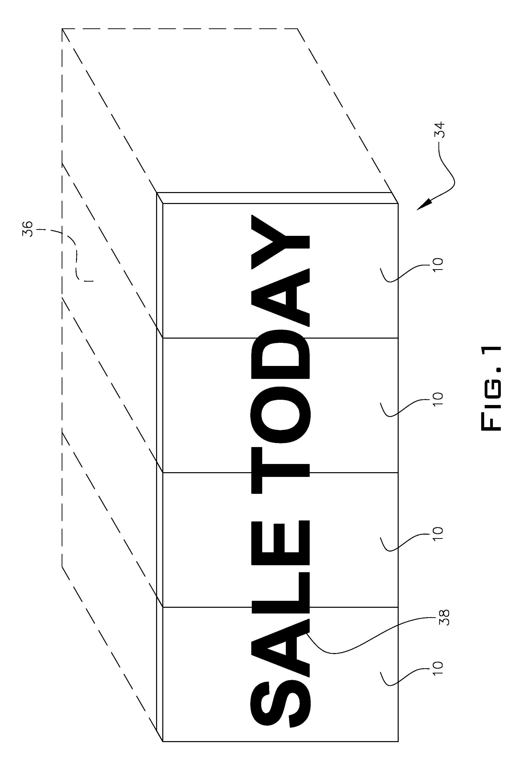
[0024]FIG. 1 is a perspective view of a message display sign utilizing modular panels of the present invention, said message display sign having a virtual screen s represented by dashed lines thereon;

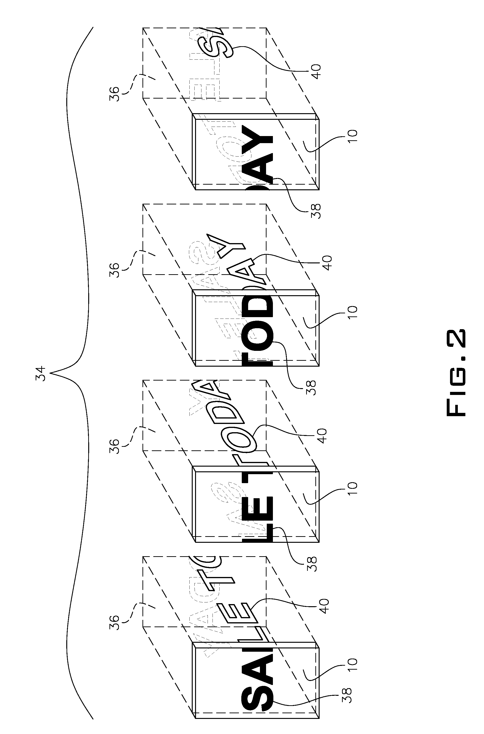
[0025]FIG. 2 is an exploded view of the invention depicted in FIG. 1 wherein the virtual screen is once again represented by the dashed lines and wherein it is shown that a message to be displayed on said sign with said virtual screen is fully rendered on each modular panel even though at any given time only a portion of said message is displayed on an LED matrix on each modular panel of said sign;

[0026]FIG. 3 is a block diagram illustrating modular panels of a message display sign of the present invention which are coupled to a host controller that sends data along a single serial data line to said modular panels wherein different commands and data can be contained in sai...


PUM


Abstract

A plurality of common, modular panels attach to a support frame carrying power and data connections for an electronic display sign. LEDs are used as the light mechanisms for illumination of said sign. Each modular panel is under separate microcontroller control and includes its own on-board memory. The electronic display sign includes a master control element that connects to a PC or laptop computer for loading data or programs into the memory of each modular board. The master control sends out commands or data that is interrogated by every microcontroller on each modular panel of the entire sign such that only the panel with a unique identification number will process data intended therefore. The on-board memory allows for the creation of a virtual screen such that each modular panel of the entire sign is rendering the entire message being displayed on said sign even though each modular panel may only be actually illuminating a portion of said message on the LEDs of each panel. A novel auto-baud scheme re-sets the baud rate for the sign for each packet of data received. A novel identifier assignment scheme allows the end user to assign serial numbers to each panel after the sign is attached to the support frame.

Description

BACKGROUND OF THE INVENTION[0001]1. Field of Invention[0002]The present invention relates to electronic sign, display and messaging systems. More particularly, it relates to a modular system having a plurality of identical modular panels forming a larger display matrix, each modular panel being under microprocessor control for selecting information for its respective module from a single, common serial data transmission line; each module microprocessor having read only memory for storing previously loaded data, temporary random access memory for retaining “virtual screen” data and computational abilities for facilitating the manipulation of said virtual screen data utilizing said previously loaded and stored data; each modular panel being able to accept a unique identifier through a method of assigning said identifier.[0003]2. Description of the Prior Art[0004]Electronic message and display systems are well known in the prior art. They first appeared outside of banks displaying the ...

Claims


Application Information

Patent Timeline
Patent Type & Authority Patents(United States)
IPC IPC(8): G08B5/22
CPCG09G3/32G09F9/3026G09G2300/026
Inventor MASKENY, DONALD DWEST, JEFFERY L
Owner MASKENY DONALD D
Why Eureka
Try Eureka