Method for controlling the cut register in a web-fed rotary press

a rotary press and cut register technology, applied in the direction of web handling, instruments, transportation and packaging, etc., can solve the problems of increasing the probability of failure of the control of the cut register, complicated control system with cascade structure, etc., and achieves the effects of low cost, high accuracy, and simple control system

Inactive Publication Date: 2009-02-24
MANROLANAD AG
View PDF15 Cites 2 Cited by
  • Summary
  • Abstract
  • Description
  • Claims
  • Application Information

AI Technical Summary

Benefits of technology

[0005]An object of the present invention is to provide a method for controlling the cut register in a web-fed rotary press that minimizes the cut register error, i.e., the deviation of the position of the cut from a predefined desired value, in the most simple, cost-effective and reliable manner with high accuracy.
[0016]The cut register setting element used can be the press unit in which the printing material is printed, in that the rotational speed of the impression cylinders is changed for some time in order to adjust the cut register. However, the method according to the invention can be applied equally well to presses in which setting elements of another type are provided on their own or in addition to the press unit for the purpose of cut register setting. In the event of a change in the rotational speed of the impression cylinders of a press unit, it is expedient to change the rotational speed of the driven cylinders of all the following clamping points of the printing material web originating from this press unit simultaneously in such a way that, overall, the result is the same change in the circumferential speed. This achieves the situation where the adjustment of the cut register is propagated substantially more quickly then at the web running speed, specifically at approximately the speed of sound in the printing material, which shortens the reaction time of the respective cut register control loop enormously.
[0022]The particular advantage of the second basic embodiment of the invention is that it requires very little effort and can therefore be implemented cost-effectively, since it needs only a single cut mark sensor with associated signal processing electronics for the entire press, which, as compared with the cut mark measurement on each individual web or part web, means an enormous reduction in the scope of the sensors and the signal processing electronics connected downstream, and therefore an enormous saving in costs. It goes without saying that, with the omission of an individual measurement on each web, a potential greater residual error has to be accepted. For applications which do not have excessively high accuracy requirements, the accuracy of the control can, however, nevertheless be sufficient.
[0023]A further embodiment of the present invention is based on the finding that, given a constant operating speed of a press, the position of a cut remains virtually constant and therefore, for a predefined speed, a sufficient accuracy of the position of the cut can even be achieved with a static setting of the cut register, that is to say in theory even without cut register control. In the case of speed changes, that is to say in particular when running up from the setup speed to the continuous printing speed and when returning to the setup speed in the course of running down the printing operation, a comparatively large dynamic cut register error occurs. However, for a predefined time curve of the operating speed, this dynamic cut register error has a characteristic time curve, which can be reproduced well given otherwise constant operating parameters of the press.
[0027]In this case, it is advantageous to store at least some of the parameters of such an approximation function in a memory in such a way that they can be indicated to the operator of the press and can be changed manually by the operator to provide the possibility that, given the occurrence of a drift of the cut position in the course of successive printing processes, suitable adaptation of the cut register function can be carried out. The use of a mathematical approximation function, whose shape can be varied by a few adjustable parameters, is of great advantage from this point of view.

Problems solved by technology

Such a control system with a cascade structure is complicated and in particular requires a large number of sensors to register the actual values of the positions of the cut on the individual part webs and also on each folded strand.
This is not only costly but as the number of sensors used rises, the probability of failure of the cut register control also increases, since failures of automated systems are generally caused to a predominant extent by sensor failures.

Method used


Image

  • Method for controlling the cut register in a web-fed rotary press
  • Method for controlling the cut register in a web-fed rotary press
  • Method for controlling the cut register in a web-fed rotary press

Examples


Embodiment Construction

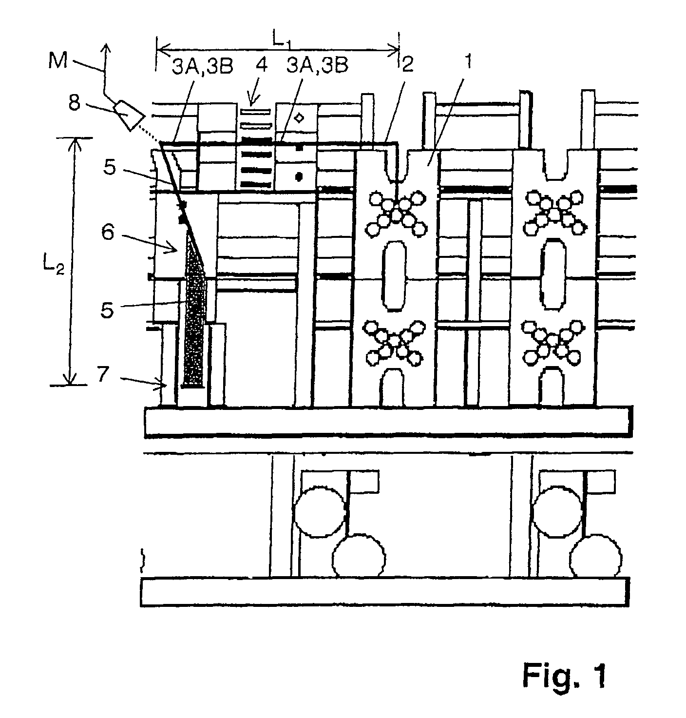
[0042]A brief overview of the path of a printing material in a press is shown in FIG. 1, to the extent to which it is important for the present invention. As FIG. 1 shows, a press normally has a plurality of press units, wherein each of the press units prints on a printing material web. In FIG. 1, for the purpose of simplification, only the web 2 printed in the press unit 1 is illustrated after leaving the press unit 1.

[0043]The web 2, like the webs coming from the other press units, is first of all cut longitudinally into two part webs 3A and 3B. Only one part web 3B of the two part webs 3A and 3B is turned in a turner unit 4, before the two part webs 3A and 3B are combined with other part webs coming from other press units but not illustrated to form a strand 5 and the latter is folded at a former 6. As a result of the folding at the former 6, the strand 5 is rotated through 90° and then runs to a knife cylinder 7, where it is cross-cut into individual sections. In the process, th...


PUM

PropertyMeasurementUnit
path lengthaaaaaaaaaa
rotational speedaaaaaaaaaa
speedaaaaaaaaaa

Abstract

A method for controlling the cut register in a web-fed rotary press, includes registering an actual value measurement of a position of cut register marks on a printed material web by measuring positions of printing cut register marks on the printed material web, using the measured positions in control loops as actual values of positions of cuts for cut register control, and correcting a first set value of a cut register setting element assigned to the printing material web based on a mathematical model for an error contribution of a proportion of the path of the printing material web that is not registered by the actual value.

Description

BACKGROUND OF THE INVENTION[0001]The invention relates to a method for controlling the cut register in a web-fed rotary press and a computer program for cut register control.[0002]DE 199 36 291 A1 describes a method for determining the positions of cuts of part webs of a longitudinally cut printing material web in a web-fed rotary press, in which the part webs are combined into strands, these are each folded on a former and are finally crosscut by a knife cylinder. In a departure from the aforementioned document, here the cut individual web halves are designated part webs and the cut webs combined after the former are designated strands. The positions of the cuts determined are used to control the cut register, a dedicated control loop being provided for each part web and, in addition, an outer control loop for the already folded strand. The intention is to make it possible to keep the positions of the cuts of all the part webs of each folded strand at a desired value in each case.[...

Claims


Application Information

Patent Timeline
Patent Type & Authority Patents(United States)
IPC IPC(8): B41F13/56B41F13/54G06F19/00
CPCB65H23/1886B65H2301/4148B65H2801/21
Inventor THEILACKER, KLAUS
Owner MANROLANAD AG
Why Eureka
Try Eureka