Hydraulic controlling device of working machine

a hydraulic control and working machine technology, applied in the direction of clutches, fluid couplings, constructions, etc., can solve the problems of generating shock, and reducing the amount of oil supplied to each actuator, so as to reduce the rotational speed of the engine and prevent pressure interference. , the effect of improving the operation of the actuator

Active Publication Date: 2009-03-03
KOBELCO CONSTR MASCH CO LTD
View PDF11 Cites 7 Cited by
  • Summary
  • Abstract
  • Description
  • Claims
  • Application Information

AI Technical Summary

Benefits of technology

[0024]Accordingly, it is an object of the present invention to provide a hydraulic controlling device of a working machine that can reliably prevent pressure interference (improper operation of actuators) occurring when carrying out a combined operational process and caused by a reduction in the rotational speed of an engine.
[0027]According to the present invention, the hydraulic controlling device is formed so as to perform an opening controlling operation in which the opening amount of the connection path connecting the pump lines of the respective pumps with each other is reduced at the low-rotational-speed side in accordance with the rotational speed of the engine. Therefore, it is possible to reliably prevent pressure interference (which causes work such as raising a boom to be performed very slowly or which prevents such work from being performed) from occurring when performing a combined operational process in a state in which the rotational speed of the engine is low.
[0029]In this case, since the opening amount of the connection path of the straight travel valve itself is controlled by controlling the position of the straight travel valve, compared to, for example, a structure in which an opening of an externally provided communication valve is controlled, costs are reduced and less space is used.

Problems solved by technology

Therefore, a shock is generated.
It is known that, when a controlling device has a structure in which a plurality of actuators are driven by a common pump, pressure interference that makes it difficult for oil to flow towards high operating pressure occurs.
However, when the rotational speed of an engine is low as during low idling, the pump discharge amount is small, thereby considerably reducing the amount of oil that is supplied to each actuator.
Therefore, when carrying out a combined operational process in a state in which the engine is rotating at a low speed, the influence of the pressure interference is increased.
As a result, work, such as raising a boom, requiring a load (operating pressure) that is higher than that required for traveling is improperly performed, that is, movement becomes extremely slow or no longer occurs).
Therefore, the technology cannot be used to directly overcome pressure interference that occurs due to a change in the rotational speed of the engine.

Method used


Image

  • Hydraulic controlling device of working machine
  • Hydraulic controlling device of working machine
  • Hydraulic controlling device of working machine

Examples


Embodiment Construction

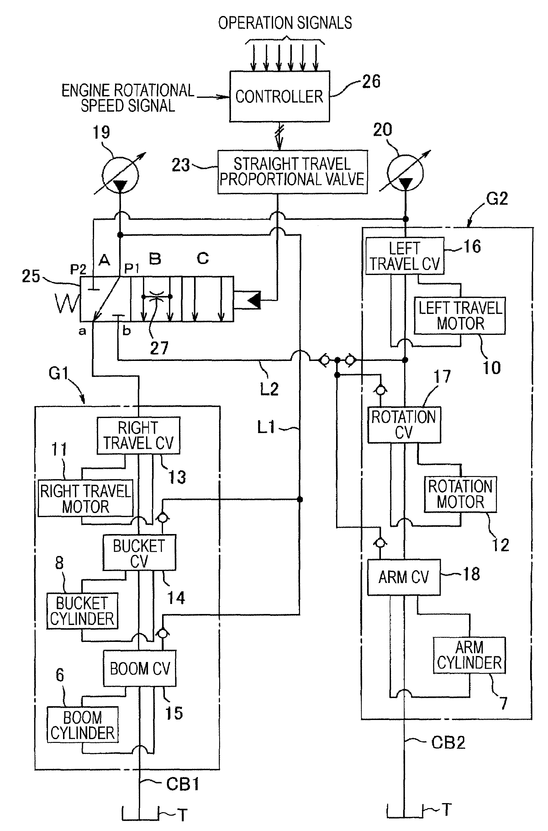
[0039]In FIG. 1 showing an embodiment, parts corresponding to those of the related hydraulic controlling device shown in FIG. 6 are given the same reference numerals and the same description of the corresponding parts will be omitted.

[0040]The embodiment shown in FIG. 1 is the same as the related device shown in FIG. 6 in that:

[0041](i) groups of hydraulic actuators are divided into a first group G1 (including a right travel motor 11, a bucket cylinder 8, and a boom cylinder 6) and a second group G2 (including a left travel motor 10, a rotation motor 12, and an arm cylinder 7), and oil discharged from a first pump 19 and oil discharged from a second pump 20 are supplied to the groups G1 and G2 through a straight travel valve 25; and

[0042](ii) a straight travel proportional valve 23 is controlled on the basis of control signals from a controller 26 to control the straight travel valve 25 by a straight travel proportional valve 23.

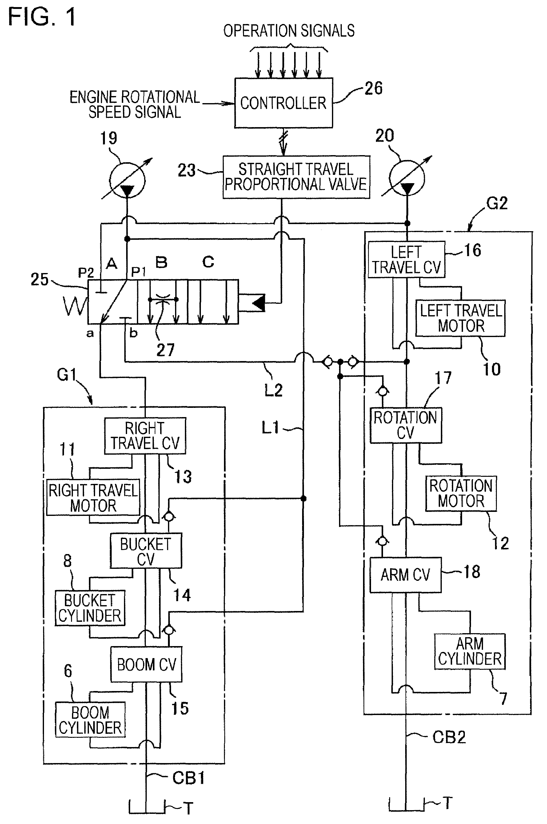
[0043]The straight travel valve 25 has a neutral posit...


PUM


Abstract

A hydraulic controlling device in which, when performing a combined operational process, a position of a straight travel valve is switched to a straight travel position to drive both a travel motor and a working actuator by separate pumps. In this case, to prevent a sudden reduction in travel speed resulting from a reduction in a flow amount at a travel side, pump lines of both pumps are connected to each other at an intermediate position by a connection path, so that a portion of oil at a working side is sent towards the travel side. With such a structure, when a rotational speed of an engine is less than a set rotational speed, an opening amount of the connection path is reduced through a straight travel proportional valve by a controller, thereby preventing pressure interference causing, for example, the working actuator to no longer move.

Description

BACKGROUND OF THE INVENTION[0001]1. Field of the Invention[0002]The present invention relates to a hydraulic controlling device of a working machine such as a hydraulic excavator.[0003]2. Description of the Related Art[0004]A related art will be described taking a hydraulic excavator as an example.[0005]As shown in FIG. 5, in the hydraulic excavator, an upper rotating body 2 is mounted on a crawler-type lower traveling body 1 so as to be rotatable around a vertical axis. In addition, in the hydraulic excavator, a working (excavating) attachment 9 including a boom 3, an arm 4, a bucket 5, and cylinders 6, 7, and 8 for raising and lowering the boom, operating the arm, and operating the bucket, respectively, is mounted on the upper rotating body 2.[0006]Left and right travel motors 10 and 11 that travel-drive the lower traveling body 1 and a rotation motor 12 that rotationally drives the upper rotating body 2 are provided (see FIG. 6).[0007]FIG. 6 shows the entire structure of a hydrau...

Claims


Application Information

Patent Timeline
Patent Type & Authority Patents(United States)
IPC IPC(8): F16D31/02
CPCE02F9/2242E02F9/225E02F9/2292E02F9/2296
Inventor UEDA, KOJI
Owner KOBELCO CONSTR MASCH CO LTD
Why Eureka
Try Eureka