Tandem-connected rotatable receptacle unit

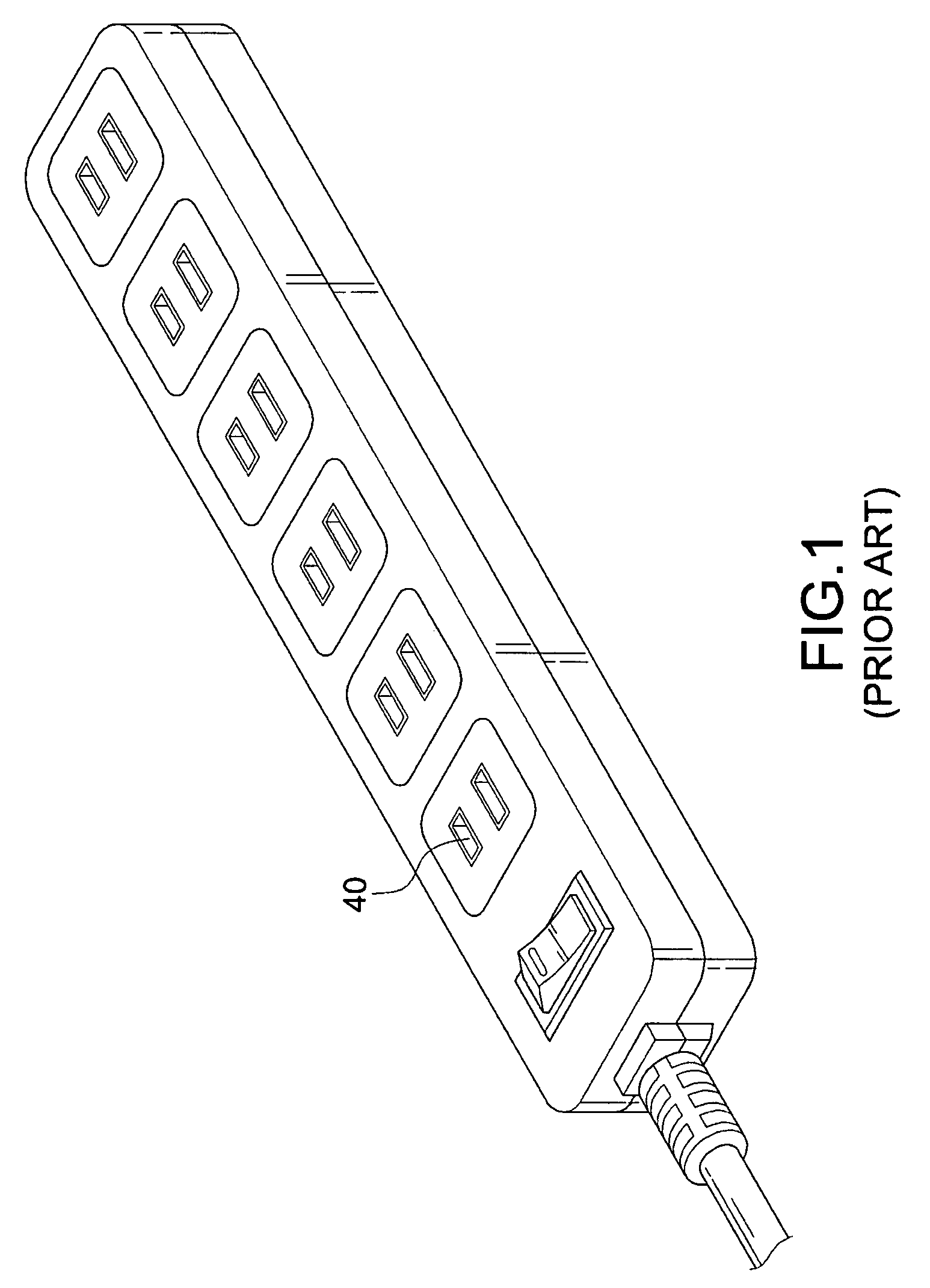
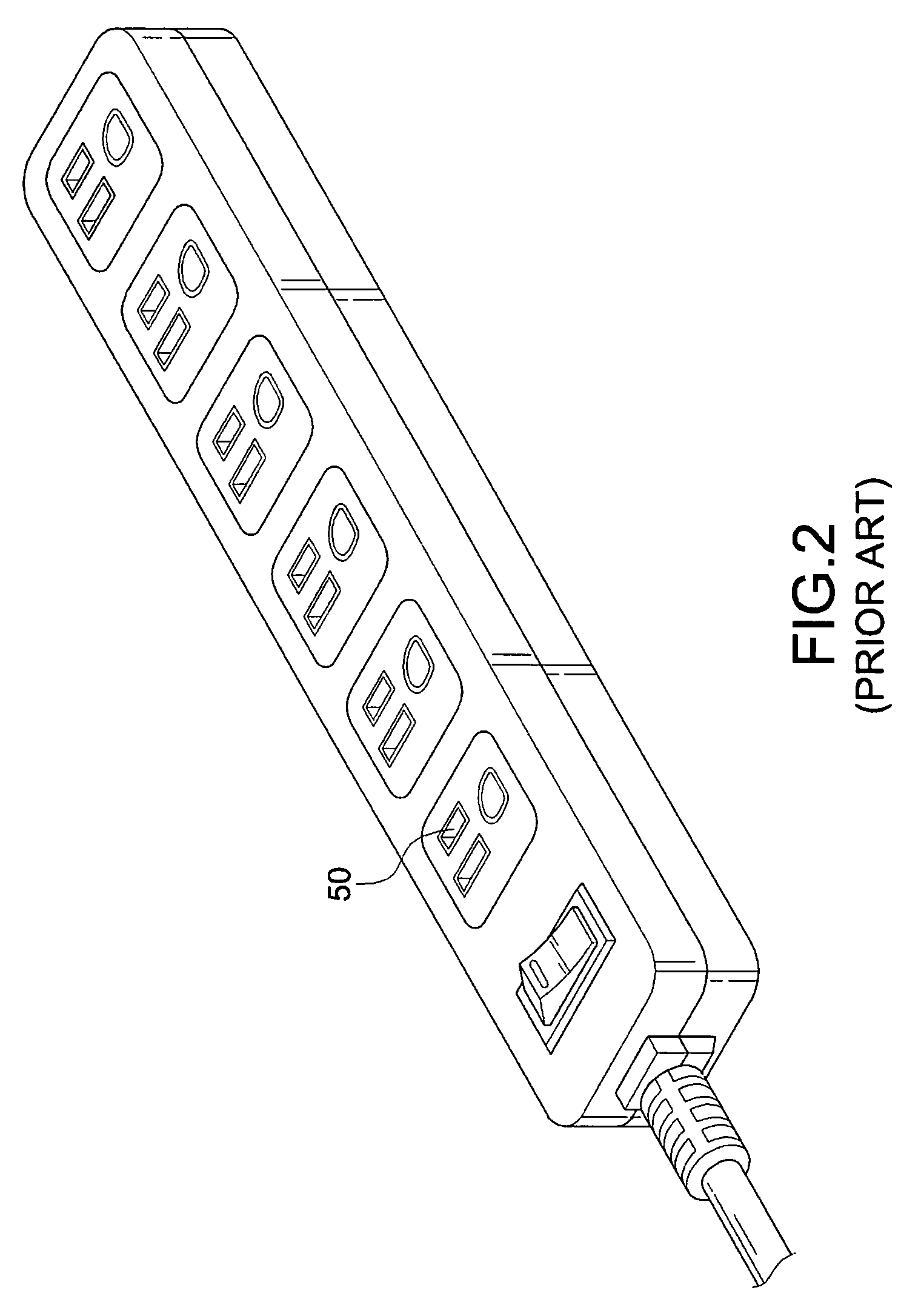
a rotatable receptacle and rotatable technology, applied in the direction of flexible/turnable line connectors, contacts, coupling device connections, etc., can solve the problems of not being able to adjust the direction of the slots not being able to achieve the adjustment of the slot direction for the conventional socket board, and being difficult for the user to obtain access to the power source, etc., to achieve the effect of convenient us

Inactive Publication Date: 2009-03-03
MEI TZU CHIANG +1
View PDF7 Cites 59 Cited by
  • Summary
  • Abstract
  • Description
  • Claims
  • Application Information

AI Technical Summary

Benefits of technology

[0009]It is another object of the invention to provide a rotatable receptacle unit having independent receptacles that can be tandem-connected in a longitudinal and a transverse direction. Meanwhile, the receptacles can be rotated in various directions like upward, downward, rightward, and leftward. In this way, it can be avoided that the blade sets or the adapter heads interfere with each other or occupy the adjacent slots. Accordingly, all of the slots can be used without any problems.

Problems solved by technology

As a result, it is not easy for them to obtain access to power source.
As a result, the adjustment of the direction of the slots is not possible for the conventional socket board.
Therefore, it's much unpractical for the inserting action.
That is, the plug and the electric cord are undesirably twisted.
For a serious case, the power cords of different household appliances are cluttered such that the user can be considerably bothered.
Another problem of the above-mentioned fixed type extension cable with a multiple socket is that an unnecessary space is occupied when the user requires only one socket and the other five or more sockets are not detachable.

Method used


Image

  • Tandem-connected rotatable receptacle unit
  • Tandem-connected rotatable receptacle unit
  • Tandem-connected rotatable receptacle unit

Examples


Embodiment Construction

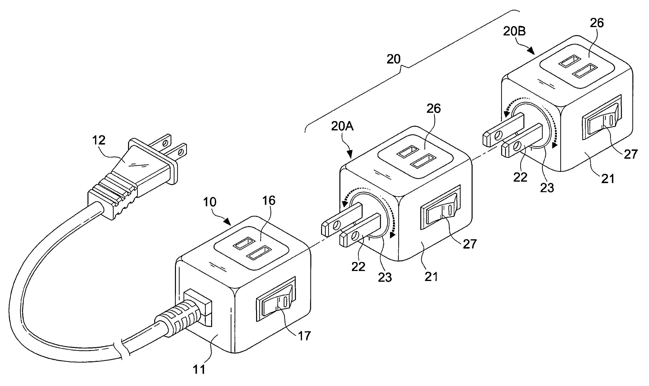
[0030]Referring to FIGS. 3 and 4, a preferred embodiment of the invention includes a primary receptacle 10 and at least one tandem connection receptacle 20A, 20B, 20C, 20D, etc.

[0031]The primary receptacle 10 includes a housing 11. An electric plug 12 with an electric cord is disposed at the front end of the housing 11 for obtaining power to enable the function of the primary receptacle 10. A first slot set 15 is formed at the rear side of the primary receptacle 10 for the output of power. According to the embodiment, the electric plug 12 has two blades while the first slot set 15 includes two slots. However, it should not be restricted thereto. In other words, three blades and three slots are also possible.

[0032]All of the tandem connection receptacles 20A, 20B, 20C, 20D have the same structure. The number of the tandem connection receptacles is variable according to different requirements to form a complete two-slot tandem connection receptacle assembly 20. The tandem connection r...


PUM


Abstract

A tandem-connected rotatable receptacle unit is provided. The unit includes a primary receptacle having a housing, an electric plug with an electric cord disposed at the front end of the housing, and a first slot set formed at the rear side of the primary receptacle for the output of power. The unit further includes at least one tandem connection receptacle having a blade set at the front side of the housing, the blade set being fixed at a round seat. The blades of the blade set are each coupled to a conducting wire electrically coupled to a conducting piece of a first slot set at the rear end of the tandem connection receptacles. The tandem connection receptacle further includes a second slot set at a side wall and a projecting rib provided at the circumference of the round seat, whereby the round seat can be rotated about the round seat for adjusting the direction of a second slot set at the side wall of the housing.

Description

BACKGROUND OF THE INVENTION[0001]1. Field of the Invention[0002]The present invention relates to a receptacle, and more particularly to a receptacle that permits an independent use or a tandem connection to be a multiple socket board. Moreover, the slots in the individual receptacles are rotatable for adjusting the direction thereof.[0003]2. Description of the Related Art[0004]When a building is complete, a wall socket (receptacle) is installed on a wall at a prearranged place. However, the household appliances are various and distributed indoors at different places. As a result, it is not easy for them to obtain access to power source. Therefore, a socket board with an extension cable is an indispensable electric element for the daily life. With the rapid development of the 3C products, such as computer / communication / consumer electronics, the personal desires are also inspired. To take a personal computer as an example, the host, monitor, printer, scanner, etc. all require power to...

Claims


Application Information

Patent Timeline
Patent Type & Authority Patents(United States)
IPC IPC(8): H01R25/00
CPCH01R13/514H01R25/003H01R31/06H01R13/70H01R35/04
Inventor MEI, TZU-CHIANGMEI, DA-PENG
Owner MEI TZU CHIANG
Why Eureka
Try Eureka