Control device for controlling electromedical appliances

a control device and electromedical technology, applied in contact mechanisms, instruments, dental surgery, etc., can solve the problems of large number of electromagnetic disturbances, large disturbance of surgical procedures being carried out in the foreground, and complicated processes, and achieve the effect of little disturbance possibility

Inactive Publication Date: 2009-03-03
ERBE ELEKTROMEDIZIN GMBH
View PDF29 Cites 28 Cited by
  • Summary
  • Abstract
  • Description
  • Claims
  • Application Information

AI Technical Summary

Benefits of technology

[0005]It is an object of the invention to provide a control device for controlling a plurality of electrochemical appliances that may include a group of said appliances that is versatile and structurally compact, with little possibility of disturbances.
[0007]The success of the invention resides in the fact that the switching means are no longer directly connected (and this includes even wireless connection of whatever kind) to the appliances or groups thereof, but rather the switching means are indirectly connected thereto by way of the allocation means, so that within the latter a particular control function, designed for particular functions of the appliances or groups thereof, can be allocated to each switching means. In this way the informational content, so to speak, of the signals produced by the switching means can be changed without altering the switching means themselves. This makes it possible not only to change the function of already installed control devices, but also to couple to one another as many control devices as desired, producing what amounts to a “keyboard”, in which the “significance of the keys” can be determined by the operator according to what is required.
[0008]The connecting means comprise a data bus designed so that after a plurality of switching means have been connected to one another, the control signals of all switching means are available at the data bus. This ensures in a simple manner that all signals from the switching means are made available simultaneously.
[0010]The information-transfer means can be connected to the appliances or groups thereof by way of a lead. Alternatively it is possible to equip the information-transfer means with at least one transmitter that can be connected to the switching means, and to provide at least one receiver connected to the appliances or groups thereof, for wireless transmission of the control signals. This eliminates the risk of “stumbling” over wires.

Problems solved by technology

This is a complicated process.
Furthermore, in some circumstances a large number of cable connections are needed, and this situation causes a considerable disturbance of the surgical procedures being carried out in the foreground, owing to both mechanical interference (“stumbling” over the cables) and electromagnetic interference caused by the many cables and control leads together acting as antennae.
The alternative of replacing the many cables by many radio links in turn causes a large number of electromagnetic disturbances.

Method used


Image

  • Control device for controlling electromedical appliances
  • Control device for controlling electromedical appliances
  • Control device for controlling electromedical appliances

Examples


Embodiment Construction

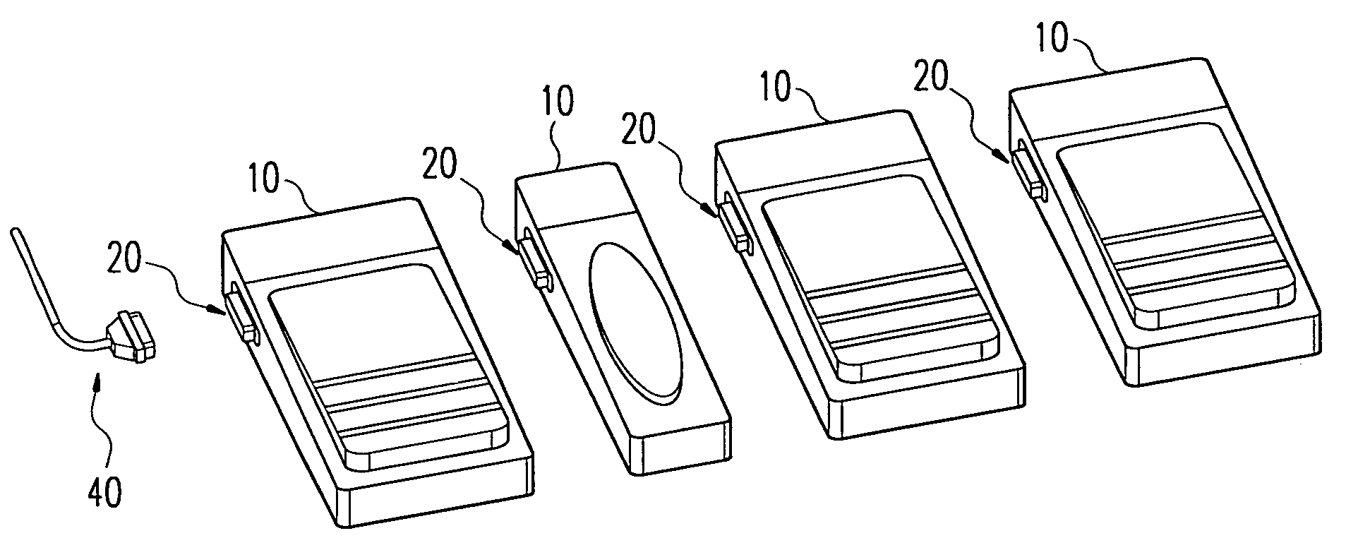
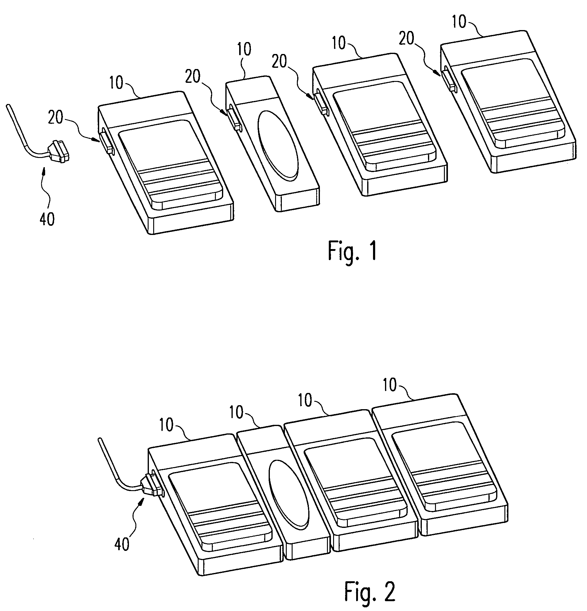
[0020]As is evident in FIG. 1, a group of pedal switches 10 is provided, each of which comprises a multi-pole connecting means 20 and (on the opposite side of the housing, not shown) a corresponding connecting means, so that the switching means 10 shown here as pedal switches can be plugged together to form a group, as is shown in FIG. 2. In addition mechanical connections are provided so that the group shown in FIG. 2, which comprises a total of four pedal switches, is firmly interconnected mechanically and so can be manipulated as a unit. For connection to the appliances that are to be controlled, which are described in greater detail below, a cable is provided to serve as information-transfer means 40.

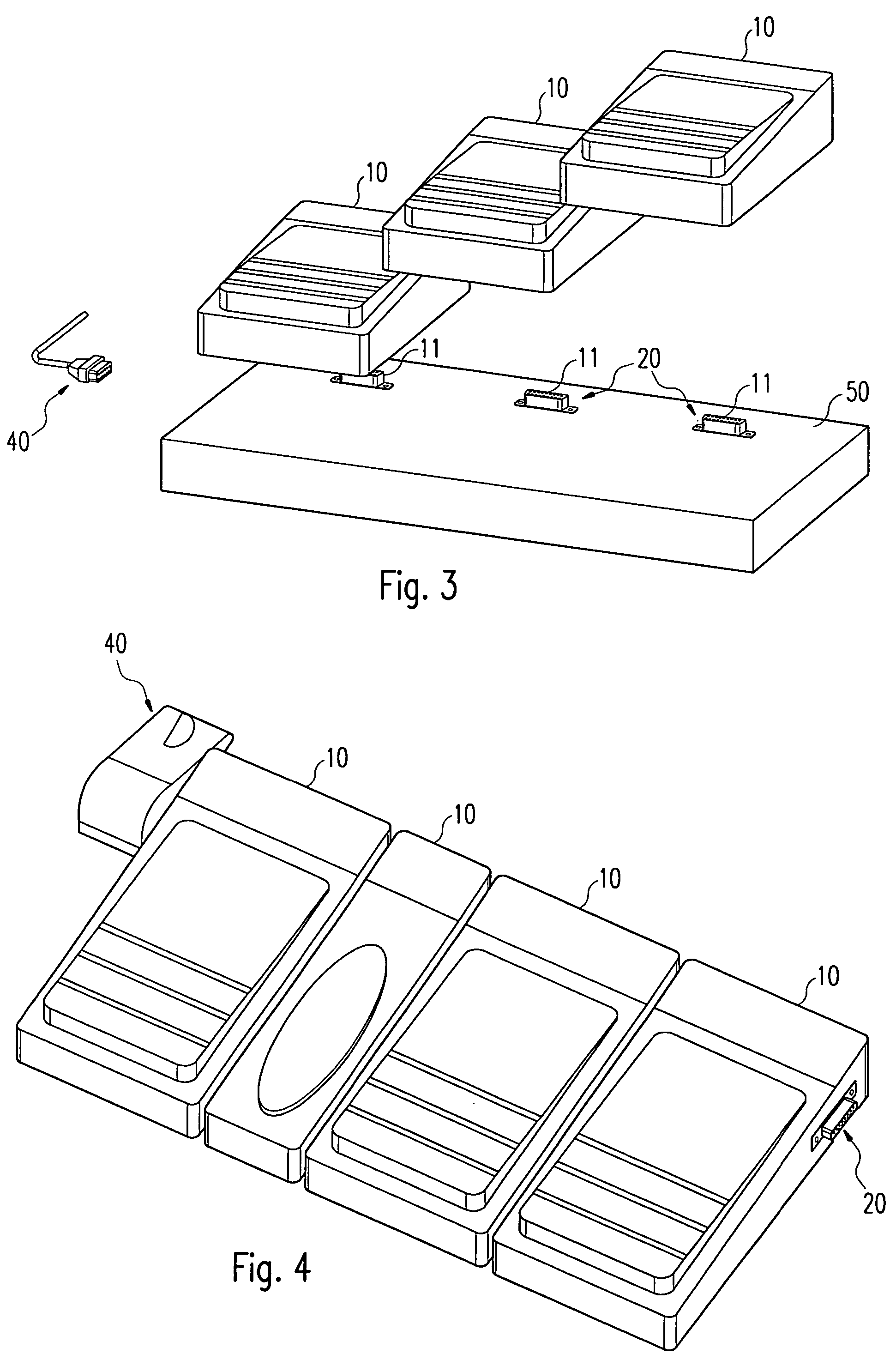
[0021]The embodiment shown in FIG. 3 differs from that according to FIG. 2 in that the pedal switches 10 are connected to one another not directly but indirectly, by way of associated plug connectors 11 in a base plate 50 that serves simultaneously as a pedestal for the group of ped...


PUM


Abstract

A known arrangement for controlling electromedical appliances or groups thereof employs foot-actuated switches or push-button switches, which are separately connected to each appliance. When it is necessary to control a large number of appliances or appliance groups, a large number of push-buttons or pedal switches is also required, the connections of which cause disturbances in the operating room. In the present invention the switching means or pedal switches are provided with connecting means by way of which the switching means can be connected to one another. Allocation means are provided in order to allocate to the control signals particular controlling functions with reference to the appliances or appliance groups. Information-transfer means transmit control signals from the switching means or pedal switches to the appliances or appliance groups.

Description

CROSS-REFERENCE TO RELATED APPLICATIONS[0001]This application is a section 371 of International Application No. PCT / EP2004 / 012261, filed Oct. 29, 2004, which was published in the German language on May 12, 2005, under International Publication No. WO 2005 / 043569 A1 and the disclosure of which is incorporated herein by reference.BACKGROUND OF THE INVENTION[0002]The invention relates to a control device for controlling electromedical appliances or groups of such appliances.[0003]In order to control electromedical appliances, such as HF generators, laser equipment, surgical instruments employing water jets or similar apparatus used in particular in an operating theater, it is necessary for switching means to be employed, in particular by the surgeon, to control the function of the attached appliances or groups thereof according to the momentary requirements. For example, to stop bleeding an APC (argon-plasma coagulation) instrument is used, in which case actuation of a pedal switch on ...

Claims


Application Information

Patent Timeline
Patent Type & Authority Patents(United States)
IPC IPC(8): H01H3/14A61B17/00A61C1/00
CPCH01H3/14A61B2017/00973A61C1/0023H01H2300/03
Inventor KUHNER, RALFHUNDT, ROLAND
Owner ERBE ELEKTROMEDIZIN GMBH
Why Eureka
Try Eureka