Collapsible rack

Inactive Publication Date: 2009-03-10
DSM IP HLDG
View PDF29 Cites 40 Cited by
  • Summary
  • Abstract
  • Description
  • Claims
  • Application Information

AI Technical Summary

Benefits of technology

[0020]It is a still further object of the present invention to provide such a device in which the shelves are made in such

Problems solved by technology

Additionally, when a rack is to be used distant from a central office, for example, at a convent

Method used


Image

  • Collapsible rack
  • Collapsible rack
  • Collapsible rack

Examples


Example

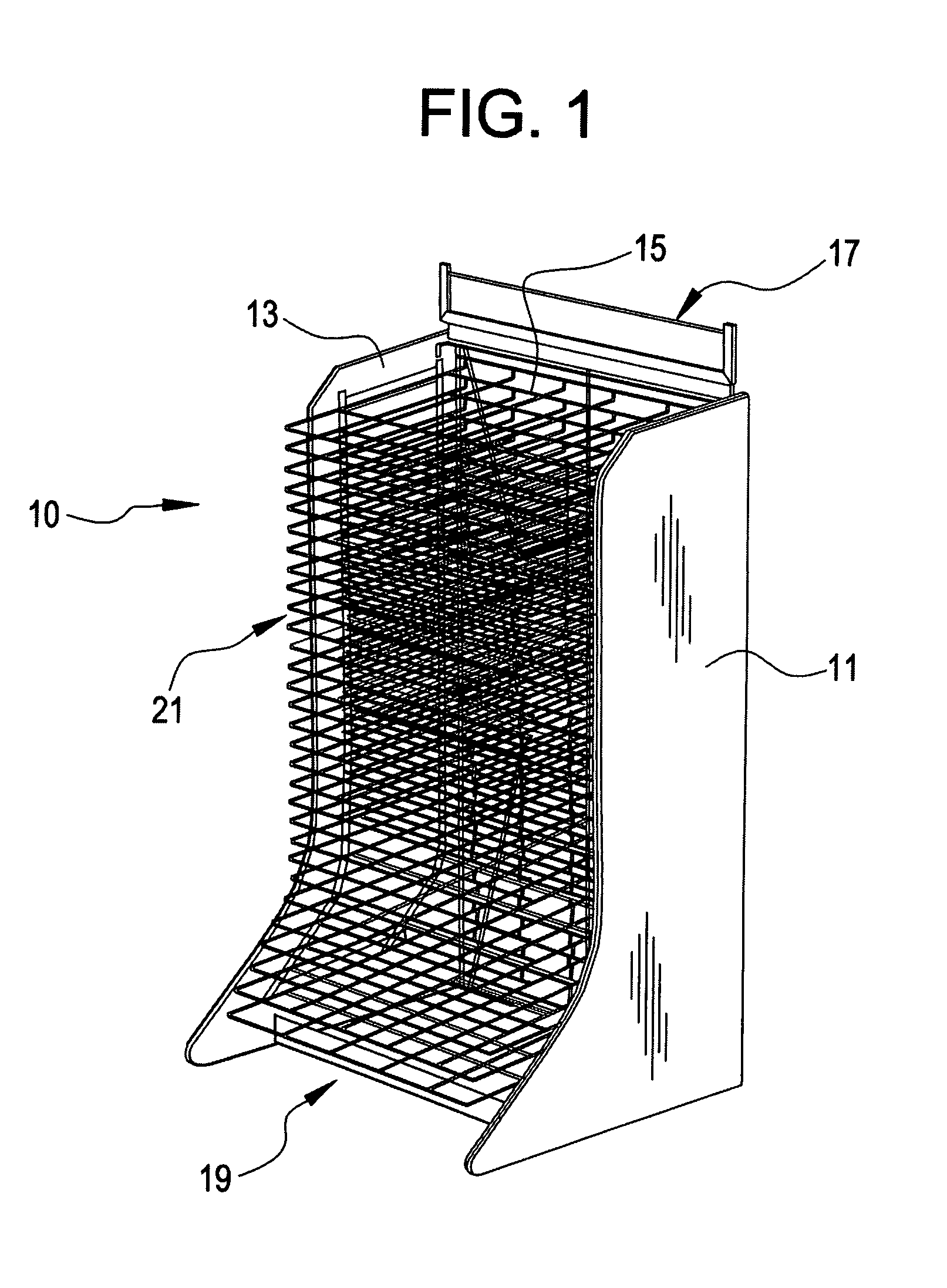
[0044]With reference, first, to FIG. 1, the present invention is generally designated by the reference numeral 10 and is seen to include side walls 11 and 13, and a rear wall 15 with opposed side edges to which the side walls 11 and 13 are hingedly or pivotably mounted to move between a first position (FIG. 16) substantially parallel to the rear wall 15 and a second position (FIG. 19) substantially orthogonal thereto. A header assembly 17 is preferably mounted on the top of the top hinges affixed to the side walls and a bottom grid assembly 19 is pivotably mounted at the bottom of the rear wall 15 in a manner to be described in greater detail hereinafter. Shelves are generally designated by the reference numeral 21 in FIG. 1.

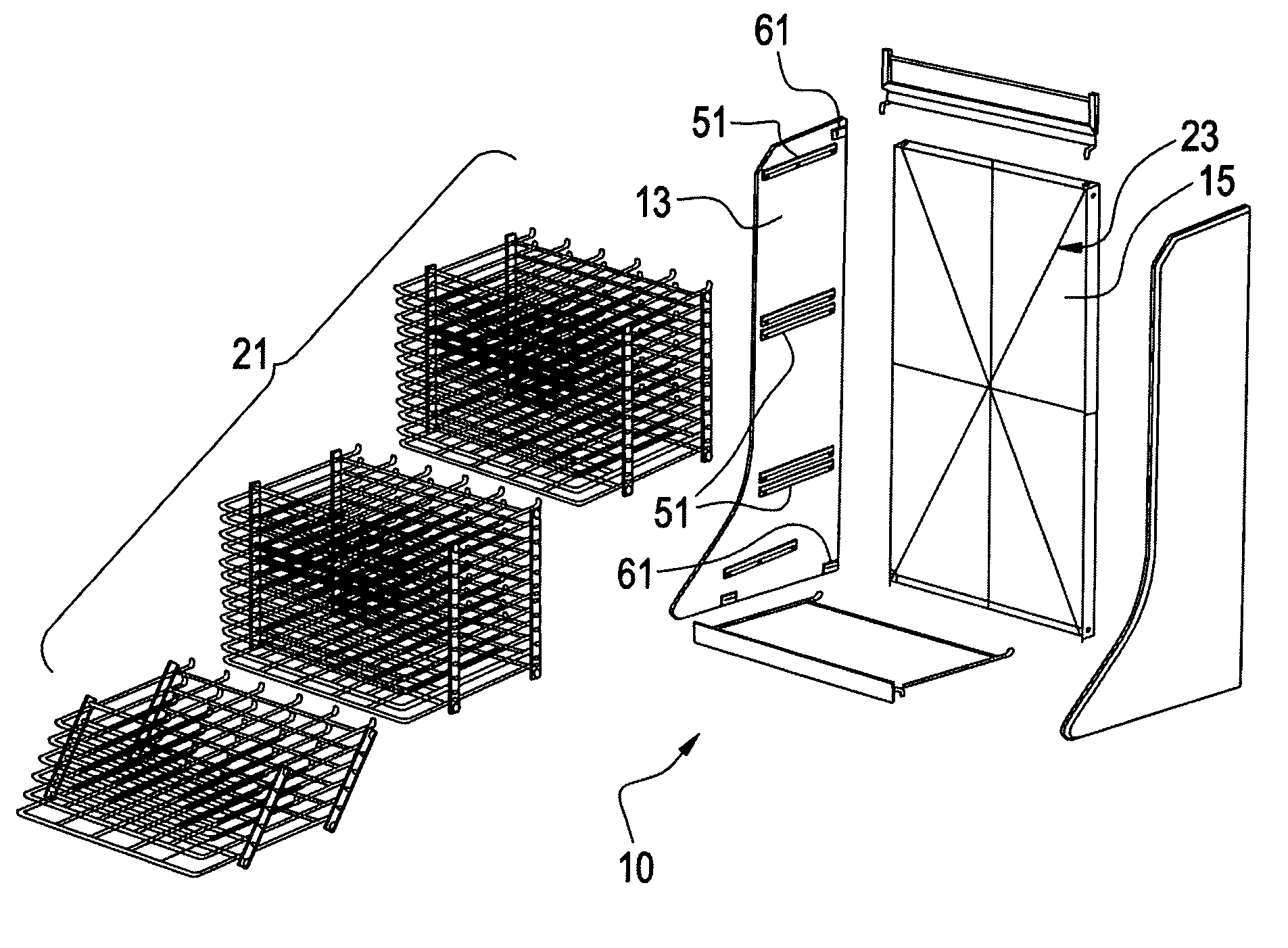
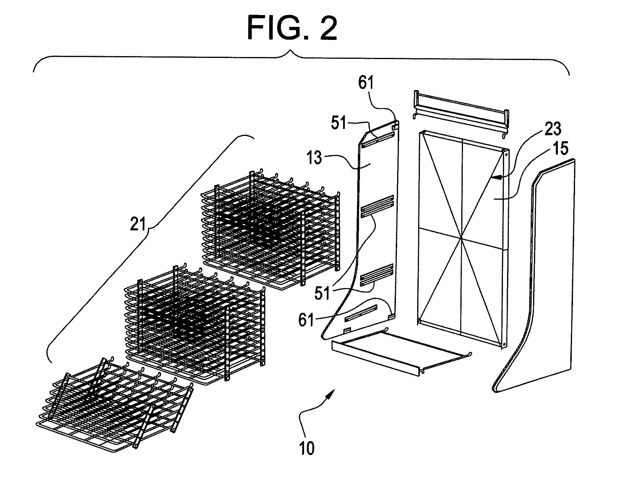
[0045]Reference is now made to FIG. 2 which shows an exploded perspective view of the collapsible rack 10. As clearly seen in FIG. 2, the rear wall 15 includes bracing generally designated by the reference numeral 23 and described in more detail with reference t...


PUM


Abstract

A rack includes a rear wall and two side walls hinged to the rear wall to pivot toward one another when the rack is being collapsed. The side walls include brackets releasably supporting shelves. The shelves are made of metal wire and may be collapsed to a flat configuration and when erected, comprise a rectangular cubic structure. The rear wall has a bottom grid assembly pivotably mounted to the rear wall so that it may be pivoted downwardly when the rack is being opened and assembled, and may be pivoted upwardly to lie flat against the rear wall for storage and transport. The walls are made of a suitable wood or particle board material or lightweight metal.

Description

BACKGROUND OF THE INVENTION[0001]The present invention relates to a collapsible rack. In the prior art, racks designed to support a variety of items for display for a variety of purposes are well known. Some such racks are intended to be assembled once using fasteners such as screws, bolts, clips, and others. Other racks have been designed as knock-down items that may be assembled for temporary use and then disassembled for storage or transport. The present invention falls into the latter category.[0002]In the prior art, while it is known to provide a rack that is easily collapsible for storage or transport, to date, Applicant is unaware of any such device in which the shelves are designed for ease of manufacture, the shelves are designed to be collapsible for easy transport, and the support structure for the shelves is also designed for easy erection, collapsing, storage, and transport.[0003]Additionally, when a rack is to be used distant from a central office, for example, at a co...

Claims


Application Information

Patent Timeline
IPC IPC(8): A47F5/08
CPCA47B43/00A47F5/13
Inventor MILLER, III, HARMON B.BUNCH, WRIGHT LANDRUM
Owner DSM IP HLDG
Why Eureka
Try Eureka