Hardtop vehicle roof with external roof kinematic system

a technology of kinematic system and hardtop vehicle, which is applied in the direction of roofs, vehicle components, transportation and packaging, etc., can solve the problems of relatively limited passenger headroom and large space consumed by kinematic system

Inactive Publication Date: 2009-03-10
MAGNA CAR TOP SYST GMBH
View PDF14 Cites 3 Cited by
  • Summary
  • Abstract
  • Description
  • Claims
  • Application Information

AI Technical Summary

Benefits of technology

[0007]An object of the present invention is a hardtop vehicle roof having multiple roof parts movable by a kinematic system between a closed position of the roof in which the roof parts cover the vehicle interior and a stored position of the roof in which the roof parts are stacked upon one another and stored within a storage compartment of the vehicle thereby exposing the vehicle interior in which the kinematic system does not encroach upon the vehicle interior when the roof is in the closed position.
[0009]In accordance with an embodiment of the present invention, a roof kinematic system is configured to move a hardtop vehicle roof having multiple roof parts between a closed position in which the roof parts cover the vehicle interior and a stored position in which the roof parts are stacked upon one another and moved away from the roof level of the vehicle to expose the vehicle interior. The roof kinematic system generally includes a roof part kinematic system for each pair of roof parts. Each roof part kinematic system articulately connects a pair of roof parts together and is operable to move the roof parts relative to one another and to the vehicle interior to move the roof between its closed and stored positions. Each roof part kinematic system includes a roof part kinematic mechanism on each of the two longitudinal sides of the roof. The entire roof kinematic system (i.e., all of the roof part kinematic systems and mechanisms) is located outside of the vehicle interior. The roof part kinematic systems movably guide the respective roof parts from the outside of the vehicle interior. As such, the kinematic elements of the entire kinematic system do not have contact with the passenger area of the vehicle interior thereby resulting in more headroom for passengers. The configuration of the roof kinematic system increases passenger safety because in the event of an accident the kinematic elements do not deform inside the vehicle interior thereby making it possible to avoid passenger injuries due to kinematic elements deforming. When the roof parts are in the closed position of the roof, the roof part kinematic systems are supported on the outside of the roof or at least to rest partly on the outside of the roof.
[0011]The rail system includes a pair of roof rail systems. Each roof rail system includes a longitudinal support (i.e., a roof rail) running in the longitudinal direction of the vehicle for mounting roof racks. Each longitudinal support is formed of at least two longitudinal support sections. The longitudinal support sections of each longitudinal support are aligned in the longitudinal direction of the vehicle. Each longitudinal support section is solidly connected with a respective roof part apiece. The longitudinal support or the longitudinal support sections may be connected with the roof parts through separated support feet. The support feet hold longitudinal support sections at a distance from the roof parts. The intermediate space between the top of the roof parts and the longitudinal supports or the longitudinal support sections facilitates the mounting of any roof racks.
[0013]In an embodiment of the present invention, at least one link of each roof part kinematic system is articulately connected with a support foot of one of the roof rail systems. This makes it possible to do without a separate fastening bracket. Each support foot holds a longitudinal support section and serves as a pivot point for a link of a roof part kinematic system.
[0015]In an embodiment of the present invention, each link of the roof part kinematic systems pivot on a pivoting extension. Each pivoting extension is preferably shaped like a flat bar and projects over one roof part in the direction of the other roof part. A further development of the present invention provides that each pivoting extension is formed by a part of a longitudinal support section. This section projects over the associated one roof part in the direction of the other roof part. That is, in the closed position, this section is located above the outside surface of the other roof part. The pivoting of the links on a pivoting extension makes it possible to arrange the links exclusively above a roof part. The roof parts are connected in the longitudinal direction through the pivoting extensions. A visually appealing way of arranging the pivoting extensions is for them to be aligned with adjacent longitudinal support sections in the closed position.
[0016]In an embodiment of the present invention, a section of each link of the roof part kinematic systems is arranged parallel to a longitudinal support when the roof is in the closed position. This makes it possible for the links to be concealed by the longitudinal support sections in the closed position. Preferably, the links pivot on the inside of the longitudinal support sections and / or support feet facing the middle of the vehicle so that they are concealed when viewed from the side of the vehicle. If the first end of a link is articulately connected with a support foot and its other end is articulately connected with a pivoting extension or a longitudinal support section, it is advantageous for the link to be essentially L-shaped. In the closed position, the longer leg of an L-shaped link is arranged parallel to a longitudinal support, and the shorter leg is arranged parallel to the support foot. The links may also be U-shaped, in order, for example, to connect two support feet or two downward pointing projections of the longitudinal support sections with one another.

Problems solved by technology

However, the kinematic systems consume a relatively large amount of space within the vehicle interior.
As such, passenger headroom is relatively limited when the roof is in the closed position covering the vehicle interior.

Method used


Image

  • Hardtop vehicle roof with external roof kinematic system
  • Hardtop vehicle roof with external roof kinematic system
  • Hardtop vehicle roof with external roof kinematic system

Examples


Embodiment Construction

)

[0031]In the figures, elements that are the same and elements having the same function are labeled with the same reference numbers.

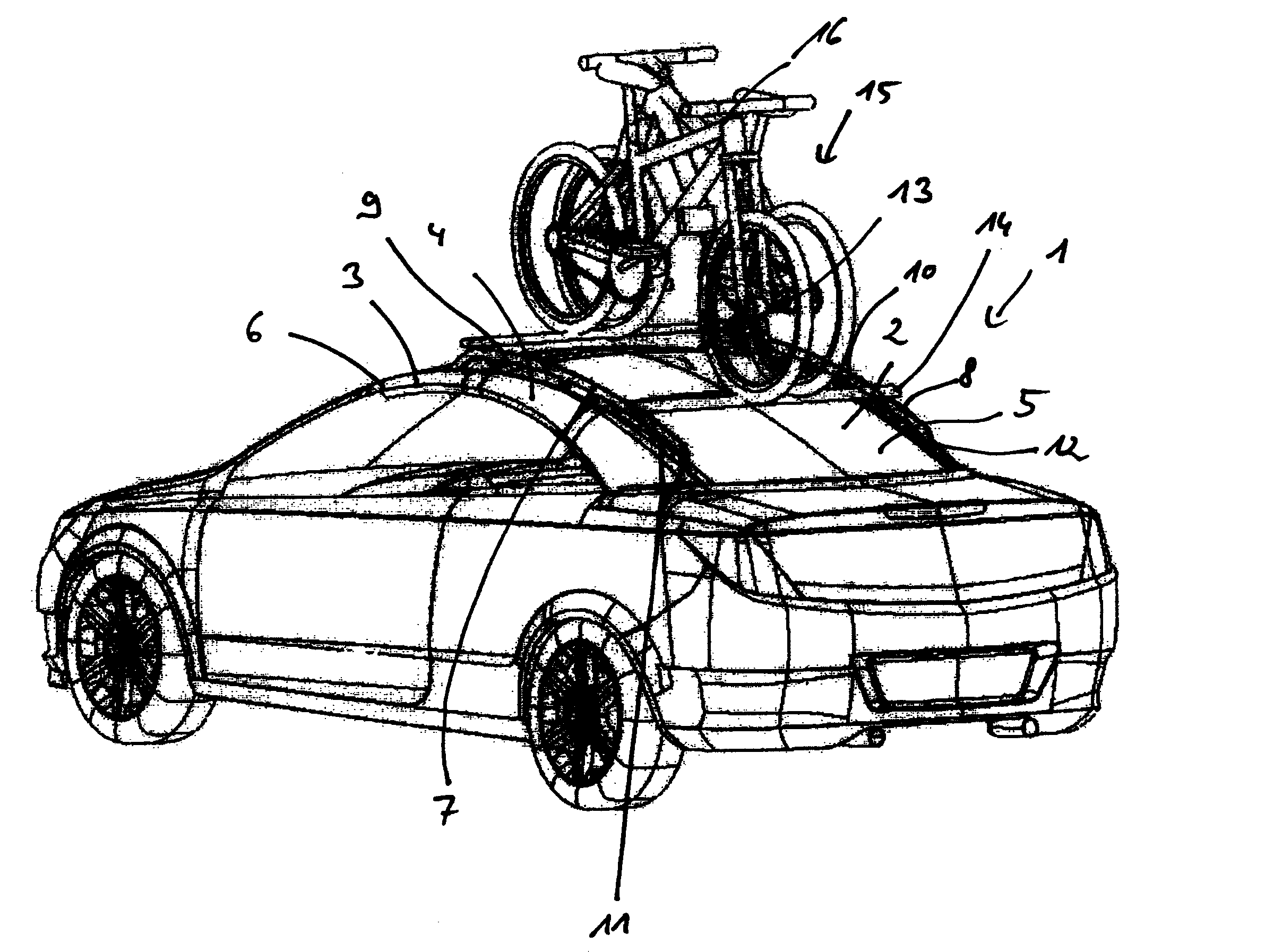
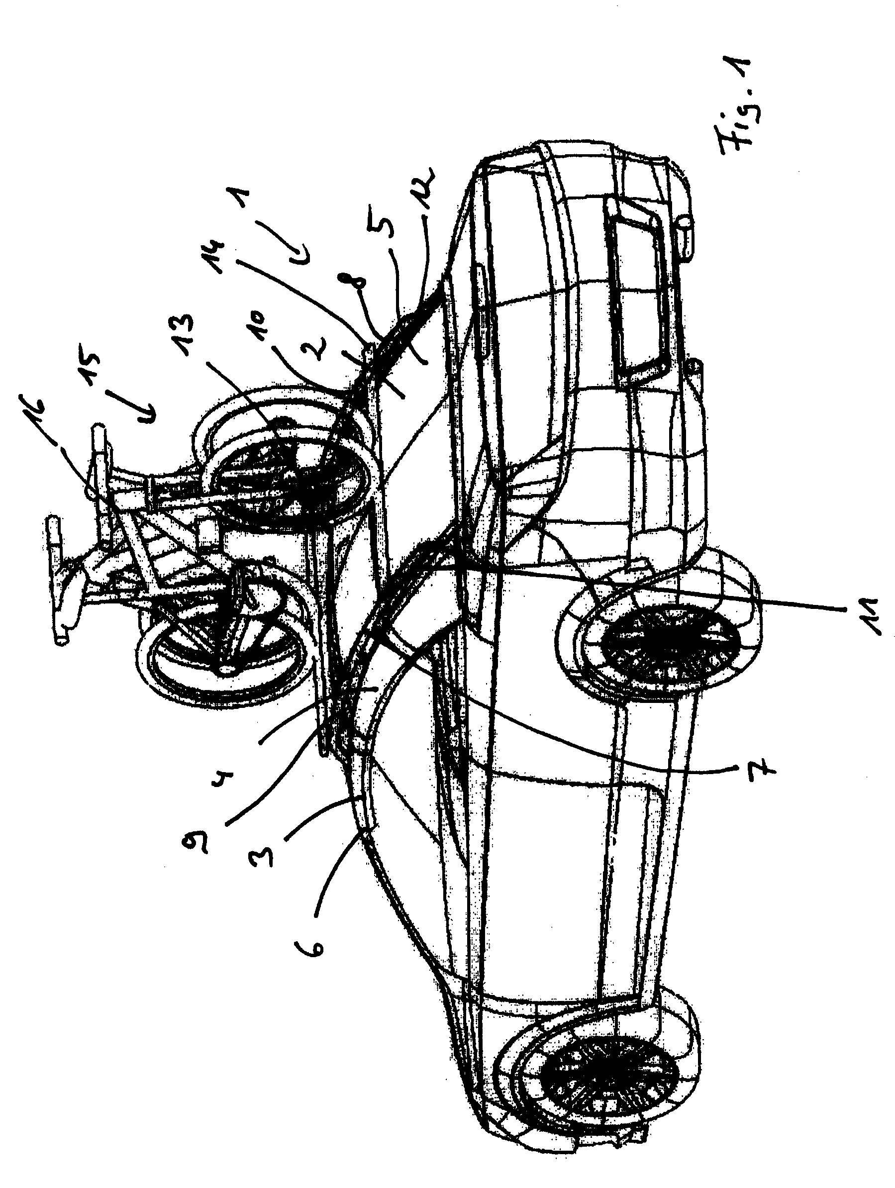
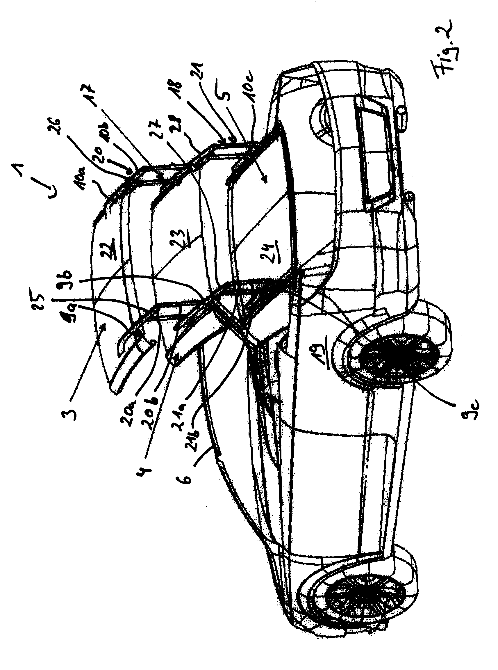
[0032]Referring now to FIGS. 1 through 6, a hardtop roof 2 for a vehicle 1 in accordance with an embodiment of the present invention is shown. Roof 2 is a three-part roof having rigid roof parts. The roof parts include a front roof part 3, a middle roof part 4, and a rear roof part 5. Front and middle roof parts 3, 4 are articulately connected to one another. Likewise, middle and rear roof parts 4, 5 are articulately connected to one another.

[0033]In general, roof 2 is movable between a closed position and a stored position. In the closed position (shown in FIG. 1), roof parts 3, 4, 5 extend over and cover the vehicle interior and are arranged flush behind one another with front roof part 3 in front of middle roof part 4 and middle roof part 4 in front of rear roof part 5 along the longitudinal direction of the vehicle. In the stored position (shown in ...


PUM


Abstract

A hardtop vehicle roof having at least two rigid roof parts, at least one of which can be adjusted, by a roof part kinematic system, between a closed position in which the vehicle interior is covered and in which the roof parts are arranged one behind the other in the direction of travel, and a storage position exposing the vehicle interior. The roof part kinematic system of the roof parts is arranged on the outside of at least one roof part facing away from the vehicle interior.

Description

CROSS-REFERENCE TO RELATED APPLICATIONS[0001]This application claims foreign priority benefits under 35 U.S.C. § 119(a)-(d) to DE 10 2005 051 647.5, filed Oct. 26, 2005, which is hereby incorporated by reference in its entirety.BACKGROUND OF THE INVENTION[0002]1. Field of the Invention[0003]The present invention relates to a hardtop vehicle roof having a plurality of roof parts in which the roof parts are movable between closed and stored positions of the roof.[0004]2. Background Art[0005]EP 1 463 647 B1 (corresponding to U.S. Patent Application Publication No. 2005 / 0156449) describes a hardtop vehicle roof having three rigid roof parts. Kinematic systems pivot the front and rear roof parts relative to the middle roof part. An adjustment kinematic system pivots the middle roof part relative to the vehicle body. In the storage position of the roof, the roof parts are laid in the same direction in a stack within a storage compartment of the vehicle. Because the roof parts are stacked ...

Claims


Application Information

Patent Timeline
Patent Type & Authority Patents(United States)
IPC IPC(8): B60J7/08
CPCB60J7/047B60J7/146B60J7/223
Inventor WEZYK, WOJCIECHKLEIN, BERTHOLDHALBWEISS, THOMAS
Owner MAGNA CAR TOP SYST GMBH
Why Eureka
Try Eureka