
Gateway plate device for a slotted mast or spar having a channel.

a technology of gateway plate and inward slot, which is applied in the direction of special-purpose vessels, marine propulsion, vessel construction, etc., can solve the problems of member sliding downwards, screw not being able to engage the threaded hole, and dragging the screw downwards, so as to achieve more headroom

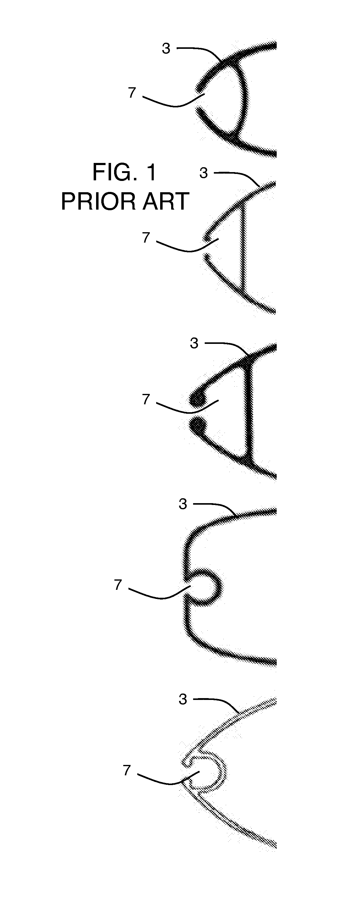
Inactive Publication Date: 2011-12-22
LUQUE TOM
View PDF4 Cites 6 Cited by
  • Summary
  • Abstract
  • Description
  • Claims
  • Application Information

AI Technical Summary

Benefits of technology

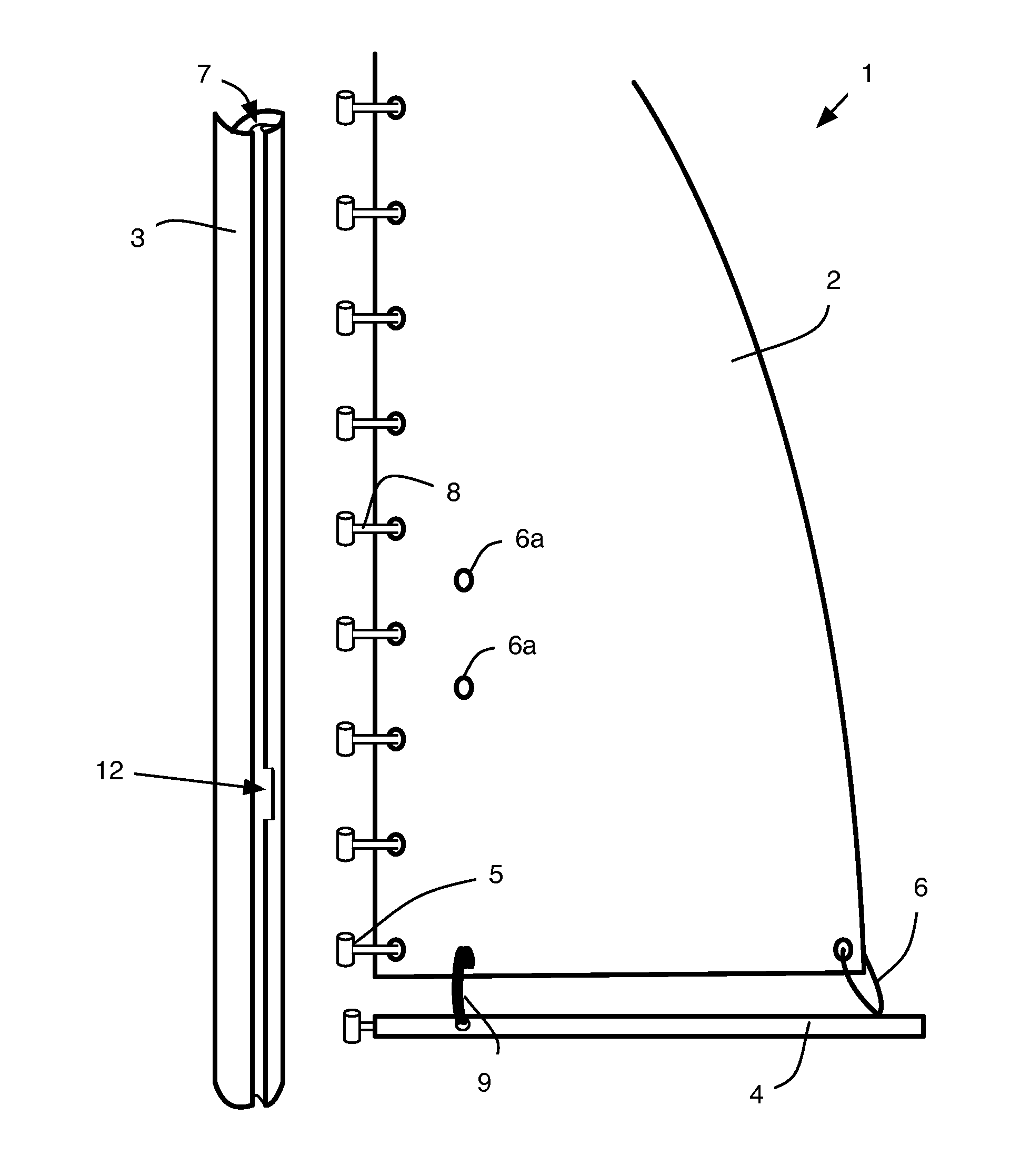
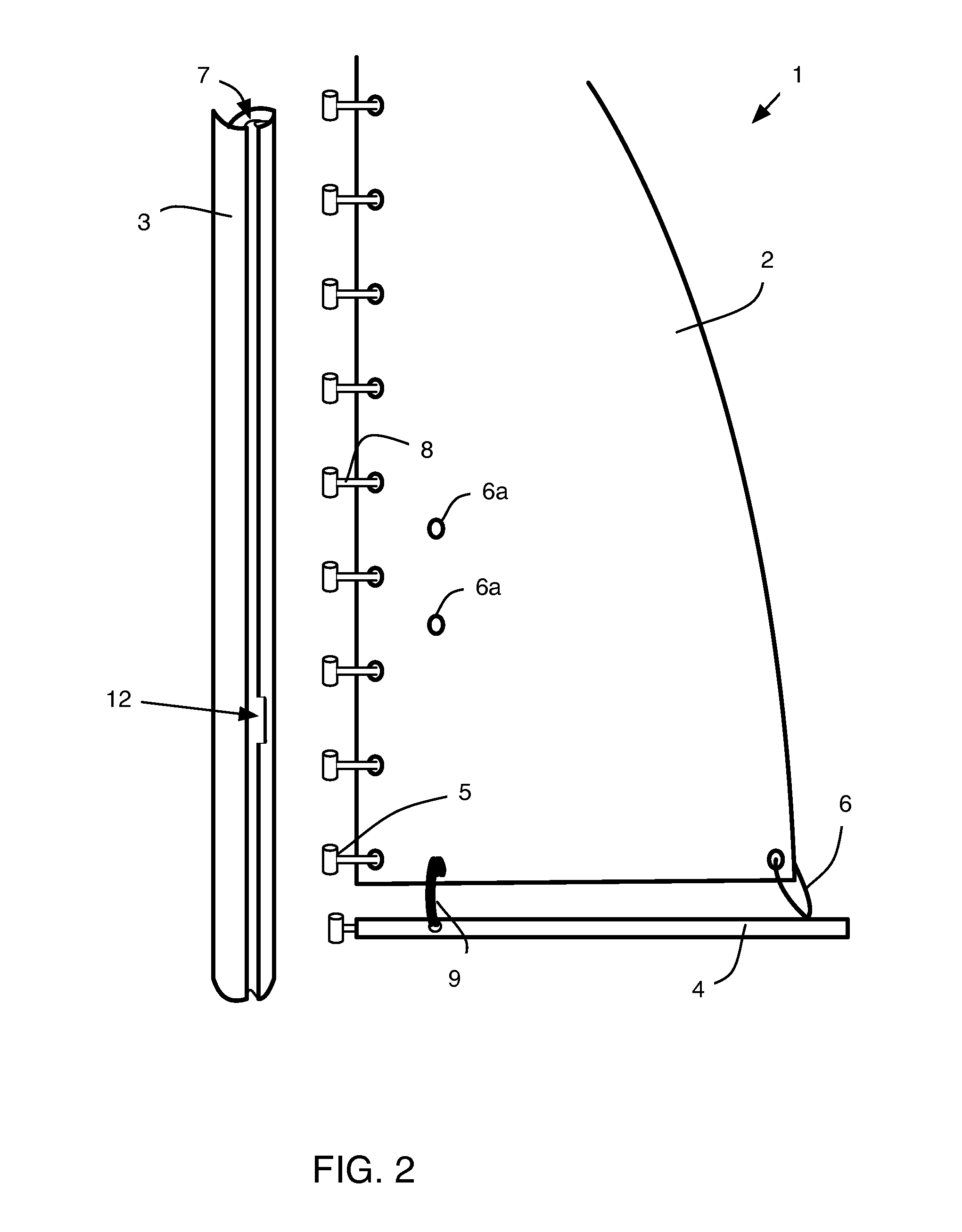
[0013]The present invention improves over the current teaching in the art and provides a device and method that can be retrofitted to existing spars having an internal track. The device consists of a one-way gate-track, that arranges over a wide aperture on a spar (such apertures being well-known in the art to load sail slugs), the device is elastically secured behind, or alternatively over, a new slot opening or preexisting sail-slot opening in spar (such as a mast) for the purpose of slidably loading sail-slugs up into a sail-track without being able to spill back out, and to reclaim the full sliding range of the track, past the slot, which would be previously lost to a open sail-slot cut out.
[0014]The present invention enables a single sailor, using just one hand, to load a sail and this is particularly useful during windy times, because it is safer and quicker to load the sail downward toward the boom so the sail is never opened to the wind. Further, since the halyard is not required, both hands are free to quickly install the sail-slugs.
[0015]Another advantage of the present invention is the elimination of a “slot stop” device, which then enables the sail to slide down to a lower profile on the boom, which, for example, reduces wind resistance, provides a less obstructed view over the boom, enables easier reefing by permitting the J-hook to reach the sail cringle. 3. J-hook reaches sail cringle for easier reefing.

Problems solved by technology

One problem highlighted by Frederiksen with this common system is that it is a rather difficult and time-consuming operation, and it is particularly difficult to bring the screw into engagement with the threaded hole.
Further, said system has the drawback that the slide member slides downwards, until it abuts the subjacent slide member, if a screw is unscrewed after the track has been mounted.
It is not possible to mount this slide member again without loosening all of the remaining slide members that have been used to fasten the track to the mast.
This operation is often very time-consuming, since slide members are sometimes used.
Yet, despite such improvements this common chore remains problematic.
And, in windy or adverse weather the task of raising a sail becomes more difficult and in certain instances can become unsafe.
For example, each time the power of the wind catches a raised sail (or partially raised sail) there is the danger of the sail flogging and the jerking of the boat, which is compounded when the boat sits atop of a trailer during setup.
And, the hazard of this task when done on the open water is even greater—thus, the current art requires at least one able-bodied sailor with two hands, or preferably, a pair of sailors with one loading the sail slugs in the slot and the second sailor maintaining force on the halyard.
But, this results in a higher vertical profile distance between the boom and the sail head, thus impeding the viewing area for the helmsman, increasing wind resistance, and requiring more canvas for making a sail cover.
Further, current methods and devices sometimes result in a missed slug.
This requires a time consuming lowering of the sail, removing each slug until the missed slug is re-fed and the raising procedure is repeated.
Also, during windy times, it is safer and quicker to load the sail downward toward the boom so the sail is never opened to the wind and many existing devices and methods do not adequately allow a sailor to load the sail in this manner.
Further limitations in the known art include, for systems that require screws, screws often fall overboard, it is hard to use a screwdriver while on water, mast and screws are different metals that cause electrolysis corrosion that eat away the threads and / or cause the screws to seize, and manipulation of known systems often require two hands.

Method used


Image

  • Gateway plate device for a slotted mast or spar having a channel.
  • Gateway plate device for a slotted mast or spar having a channel.
  • Gateway plate device for a slotted mast or spar having a channel.

Examples


Embodiment Construction

[0068]Possible preferred embodiments will now be described with reference to the drawings and those skilled in the art will understand that alternative configurations and combinations of components may be substituted without subtracting from the invention. Also, in some figures certain components are omitted to more clearly illustrate the invention.

[0069]The conventional teaching in this art instructs a head-up method of attaching a sail into the mast. This requires precision control of the main halyard with one hand, slowly raising the head of the sail up, while the other hand aligns each sail slug, in its turn, into the sail slot track, till all is pulled up in progression before installing a track-stop device above the slot opening. This conventional method, however, is problematic. For example, sometimes while admiring a raised sail, a sailor may notice a sail slug waving for your attention to unload the sail and start over again. Or, when dropping a sail, the track-stop can dis...


PUM


Abstract

An improved system for rigging a sail to a spar consists of a slot and a gateway plate. The slot is disposed on the spar to selectively enable the sail slugs to engage an internal channel. The gateway plate is adapted to selectively cover the slot and can be removed so the slugs can be inserted to or removed from the channel. The gateway plate consists of a plate body having a first and second oppositely disposed plate-hole, the plate holes having a predetermined alignment with receiving-holes on the spar, the gateway plate further includes a channel-engaging edge, an oppositely disposed handle end, and a predetermined length of elastic cord, which couples to the spar and provides positive engagement of the gateway plate against the spar when in the closed position. The gateway plate can be mounted internally or externally relative to the spar channel.

Description

PRIORITY CLAIM[0001]The present application claims benefit under 35 USC Section 119(e) of U.S. Provisional Patent Application Ser. No. 61 / 397,753 filed on Jun. 17, 2010: The present application is based on and claims priority from this application and the disclosure of which is hereby expressly incorporated herein by reference.BACKGROUND[0002]This invention relates to a gateway plate or cover for an inward slot on a spar, and more particularly an inward slot as found commonly on a mast, boom, or beam (generally and collectively, a ‘spar’) on sailing vessels having an aperture for loading and unloading cars, carriers (collectively ‘slugs’) and similar such slide member as would be used on the leading edge on a mainsail, for example.[0003]Masts for sail vessels such as sailboats have a rearward facing slot or channel for supporting a luff or leading edge of a mainsail. For example, the luff of the sail may be attached to a bolt-rope, and a circular channel having a restricted opening ...

Claims


Application Information

Patent Timeline
Patent Type & Authority Applications(United States)
IPC IPC(8): B63H9/08B63H9/10
CPCB63B15/0083B63H2009/086B63H9/08
Inventor LUQUE, TOM
Owner LUQUE TOM
Learn More