Active inductor

a technology of active inductors and inductors, which is applied in the field of active inductors, can solve the problems of large spiral inductors, limited useful frequency ranges, and the problem of requiring a relatively large voltage drop for active inductors, and achieve the effect of more headroom

Inactive Publication Date: 2005-10-25
ALCATEL-LUCENT USA INC +1
View PDF3 Cites 2 Cited by
  • Summary
  • Abstract
  • Description
  • Claims
  • Application Information

AI Technical Summary

Benefits of technology

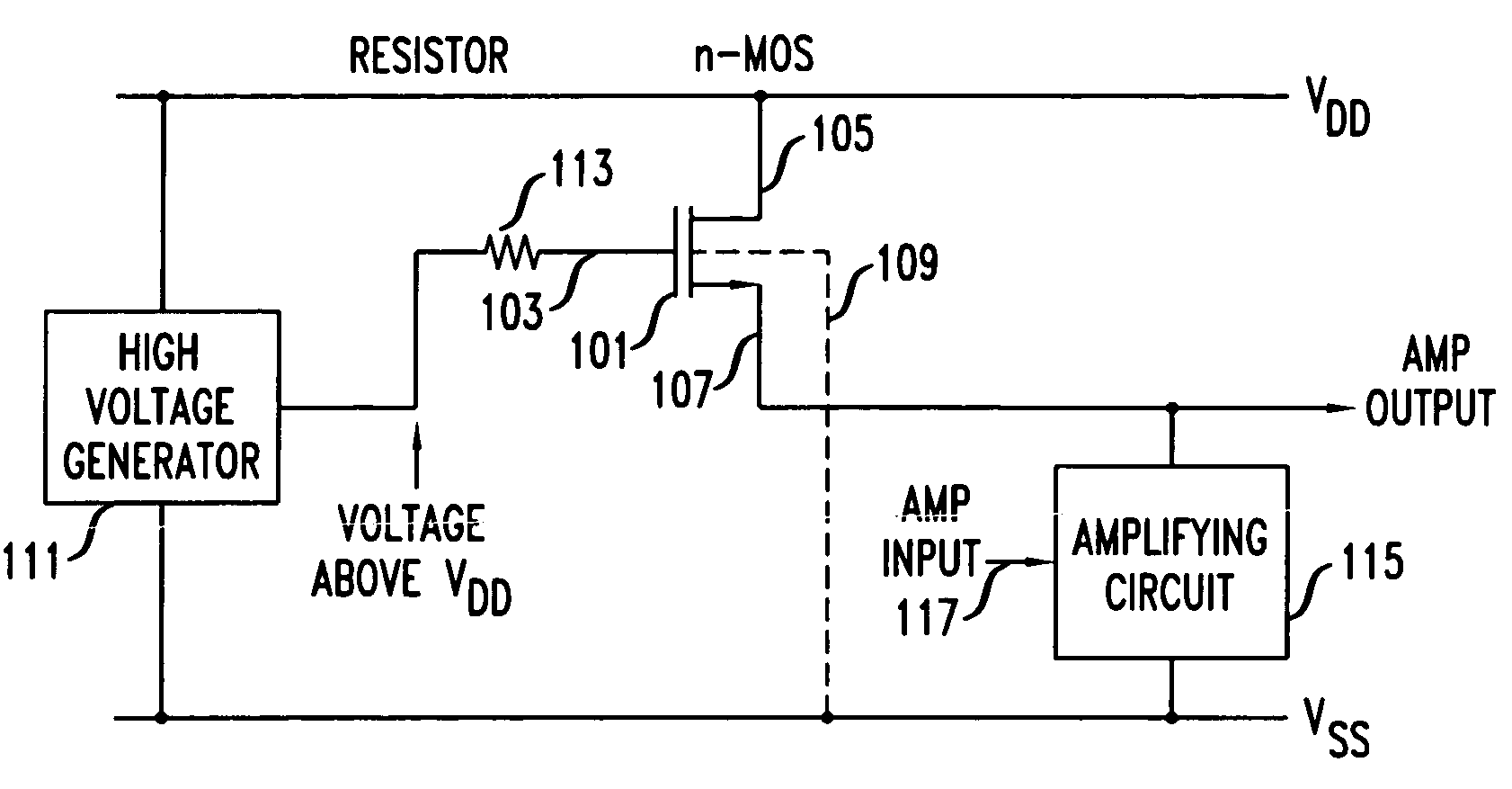
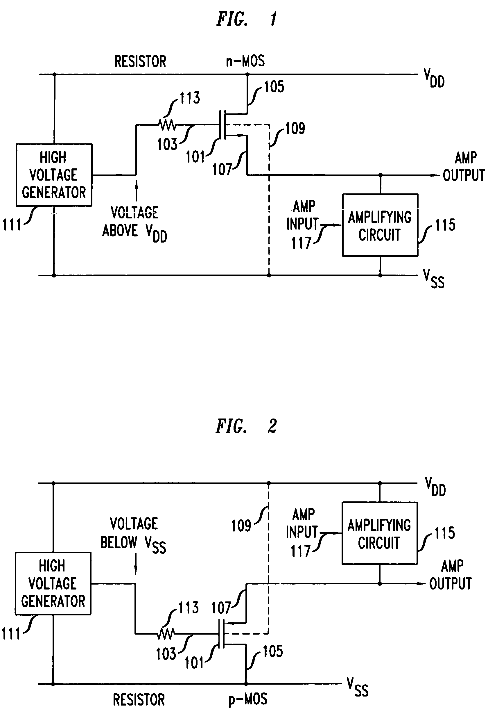
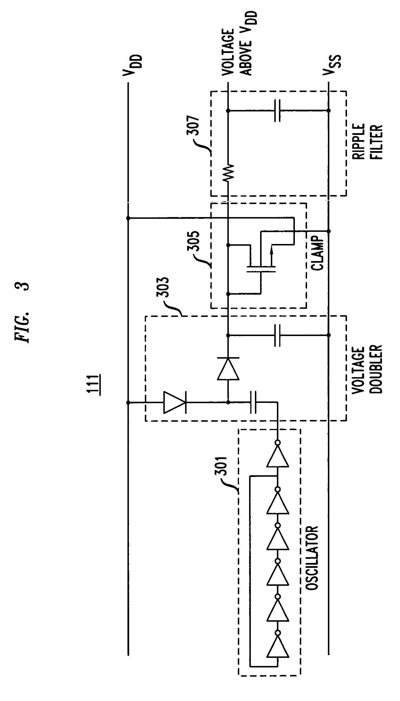
[0003]I have recognized that an active inductor with a smaller voltage drop with respect to the power supply voltage of an integrated circuit can be realized, in accordance with the principles of the invention, by an active inductor which is biased from a voltage higher than the power supply voltage, the higher voltage being generatable on the integrated circuit. Advantageously, more headroom is left for the amplifying circuit coupled to the active inductor to operate properly than with prior art active inductors. Furthermore, by not simply operating the entire active inductor from a higher voltage, the power dissipation remains the same as if the active inductor were connected as in the prior art only to the power supply voltage, and the task of generating the voltage higher than the power supply voltage is simplified, because only leakage current, e.g., nanoamps, is required.

Problems solved by technology

The problems with using a spiral inductor are that a spiral inductor is large, and its useful frequency range is limited by self resonance.
Although active inductors are small, and they typically have a greater frequency range than a spiral inductor, active inductors suffer from the problem of requiring a relatively large voltage drop, with respect to the power supply voltage, across the active inductor.
With power supply voltages decreasing, to reduce power consumption, the relatively large voltage drop of prior art active inductors becomes problematic, in that it does not leave enough headroom for the amplifying circuit coupled to the active inductor to operate properly.

Method used


Image

  • Active inductor
  • Active inductor
  • Active inductor

Examples


Embodiment Construction

[0008]The following merely illustrates the principles of the invention. It will thus be appreciated that those skilled in the art will be able to devise various arrangements which, although not explicitly described or shown herein, embody the principles of the invention and are included within its spirit and scope. Furthermore, all examples and conditional language recited herein are principally intended expressly to be only for pedagogical purposes to aid the reader in understanding the principles of the invention and the concepts contributed by the inventor(s) to furthering the art, and are to be construed as being without limitation to such specifically recited examples and conditions. Moreover, all statements herein reciting principles, aspects, and embodiments of the invention, as well as specific examples thereof, are intended to encompass both structural and functional equivalents thereof. Additionally, it is intended that such equivalents include both currently known equival...


PUM


Abstract

An active inductor with a smaller voltage drop with respect to the power supply voltage of an integrated circuit can be realized by an active inductor which is biased from a voltage higher than the power supply voltage, the higher voltage being generatable on the integrated circuit. Advantageously, more headroom is left for the amplifying circuit coupled to the active inductor to operate properly than with prior art active inductors. Furthermore, by not simply operating the entire active inductor from a higher voltage, the power dissipation remains the same as if the active inductor were connected as in the prior art only to the power supply voltage, and the task of generating the voltage higher than the power supply voltage is simplified, because only leakage current, e.g., nanoamps, is required.

Description

TECHNICAL FIELD[0001]This invention relates to the art of active inductors, and more particularly, to active inductors for use in circuits operating with a low power supply voltage.BACKGROUND OF THE INVENTION[0002]As is well known, inductors can be used to expand the bandwidth of amplifiers. When an amplifier requiring an inductor is implemented on an integrate circuit, the inductor may be implemented either as spiral inductor or as an active inductor. The problems with using a spiral inductor are that a spiral inductor is large, and its useful frequency range is limited by self resonance. Although active inductors are small, and they typically have a greater frequency range than a spiral inductor, active inductors suffer from the problem of requiring a relatively large voltage drop, with respect to the power supply voltage, across the active inductor. With power supply voltages decreasing, to reduce power consumption, the relatively large voltage drop of prior art active inductors ...

Claims


Application Information

Patent Timeline
Patent Type & Authority Patents(United States)
IPC IPC(8): H03H11/48H03H11/00H01L21/822H01L21/8234H01L27/04H01L27/06
CPCH03H11/48
Inventor SACKINGER, EDUARD
Owner ALCATEL-LUCENT USA INC
Why Eureka
Try Eureka