Connector and a connector assembly

a technology of connectors and connectors, applied in the direction of coupling parts, coupling device connections, electrical devices, etc., can solve the problems of reducing the tactile feeling of connecting operation, the operator may inadvertently place a finger on the lock arm, etc., and achieve the effect of preventing the displacement of the lock arm in the unlocking direction and good tactile feeling

Active Publication Date: 2009-03-10
SUMITOMO WIRING SYST LTD
View PDF13 Cites 6 Cited by
  • Summary
  • Abstract
  • Description
  • Claims
  • Application Information

AI Technical Summary

Benefits of technology

[0009]The free and base ends of the lock arm are covered respectively by the first and second lock protections, and the unlocking space is defined between the two lock protections. Thus, inadvertent contact with the lock arm can be prevented, and a good tactile feeling can be obtained upon performing the connection. The locked state can be canceled by operating a middle part of the lock arm through the unlocking space between the two lock protections.
[0010]A displacing direction of the lock arm being unlocked is substantially opposite to an opening direction of the unlocking space. With this arrangement, the locked state easily can be canceled by pressing the middle part of the lock arm through the unlocking space for separating the two housings.
[0011]The lock arm preferably has two beams separated from each other by a clearance that communicates with the unlocking space. A coupling couples the free ends of the beams. With this arrangement, a finger or the like can be inserted partly into the clearance between the two beams and into a central position of the lock arm with respect to the width direction. Thus, the lock arm easily can be deformed in the unlocking direction.
[0012]Bevels preferably are provided on corners of the beams facing each other and facing the unlocking space. The bevels ensure that the operator will not experience discomfort while pressing the beams with a finger.
[0013]The lock enters the clearance between the beams when the housing is connected properly with the mating housing, and the bevels preferably are behind the lock in a properly connected state. Surfaces of the beams facing the lock preferably are substantially parallel to the opposed surfaces of the lock and have no bevel. Therefore, a displacement of the lock arm in the unlocking direction can be prevented even if the two housings shake in width directions relative to each other within the range of a clearance between the beams and the lock in the connected state.
[0015]The housing or the mating housing preferably includes at least one unlocking-operation guide that faces the unlocking space when the housings are connected properly. The unlocking-operation guide projects more in the opening direction of the unlocking space than the lock arm. Thus, a finger or the like inserted into the unlocking space is guided by the unlocking-operation guide and the second lock protecting portion so that operability is improved further.

Problems solved by technology

Thus, an operator may inadvertently place a finger on the lock arm during the connecting operation.
A returning movement of the lock arm will be sluggish if the connecting operation is performed while the finger contacts a movable part of the lock arm and might reduce the tactile feeling of the connecting operation.

Method used


Image

  • Connector and a connector assembly
  • Connector and a connector assembly
  • Connector and a connector assembly

Examples


Embodiment Construction

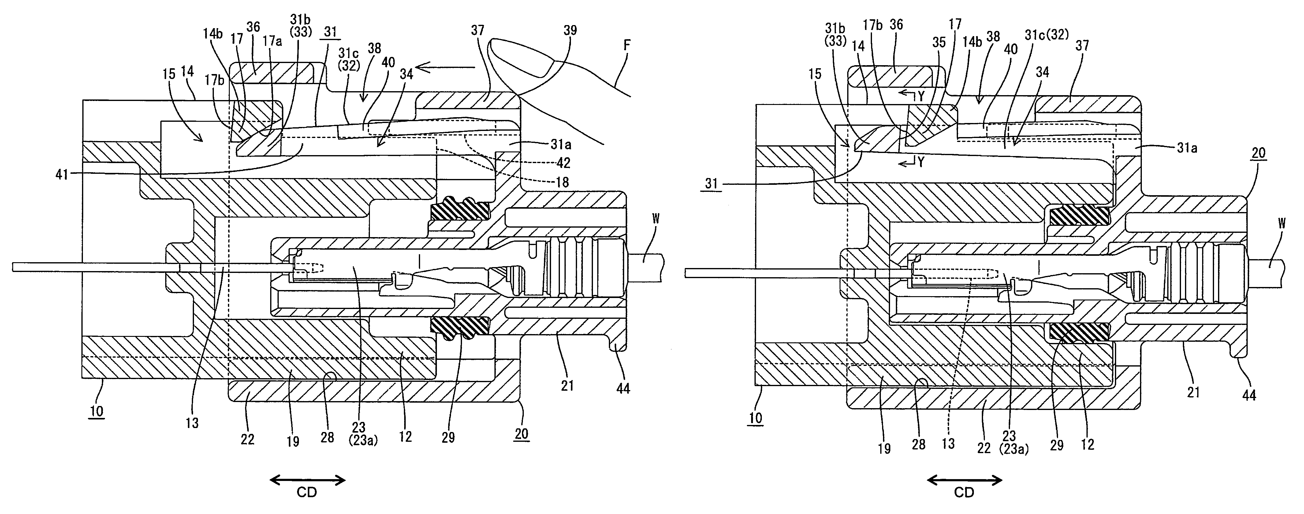
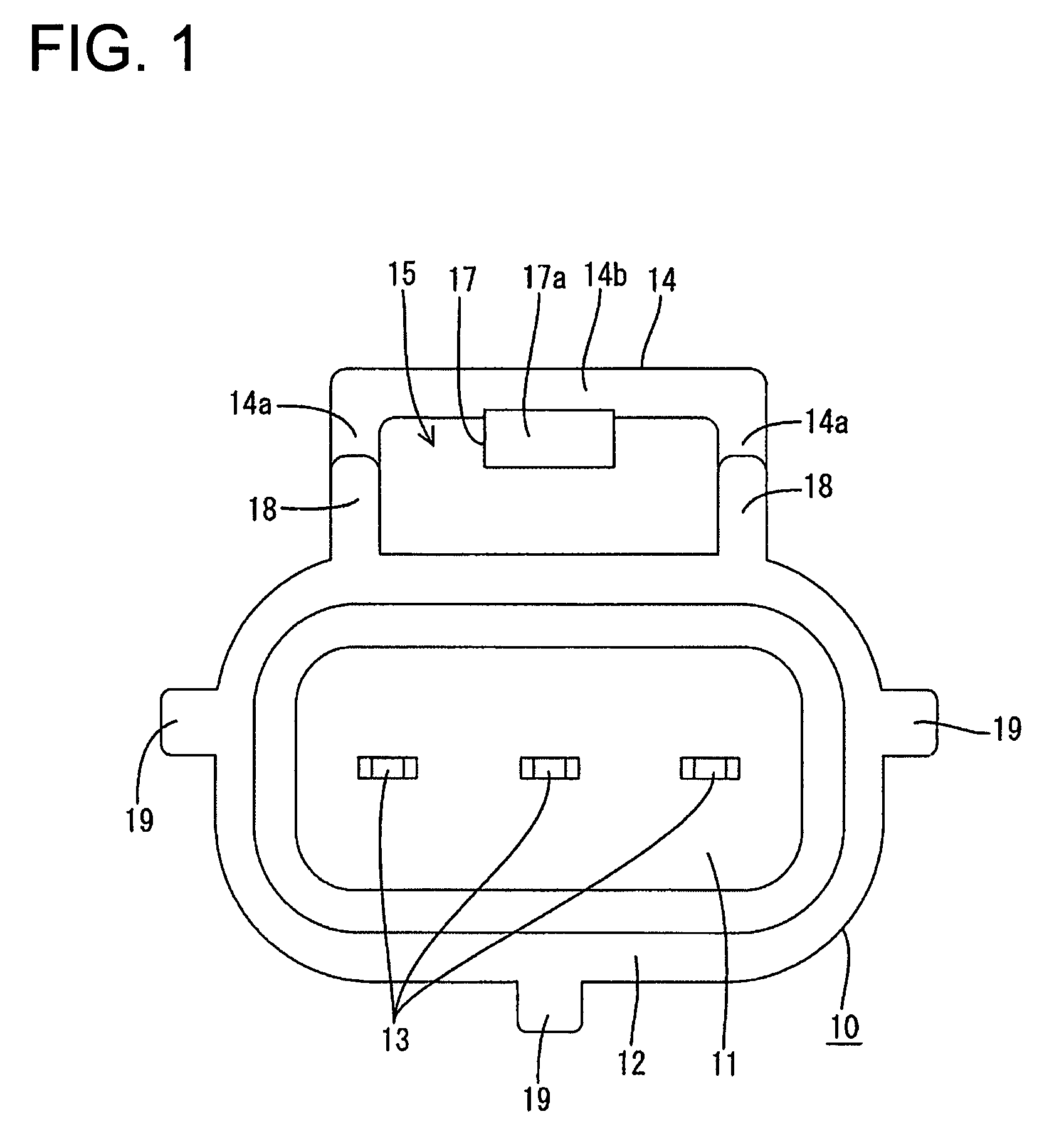
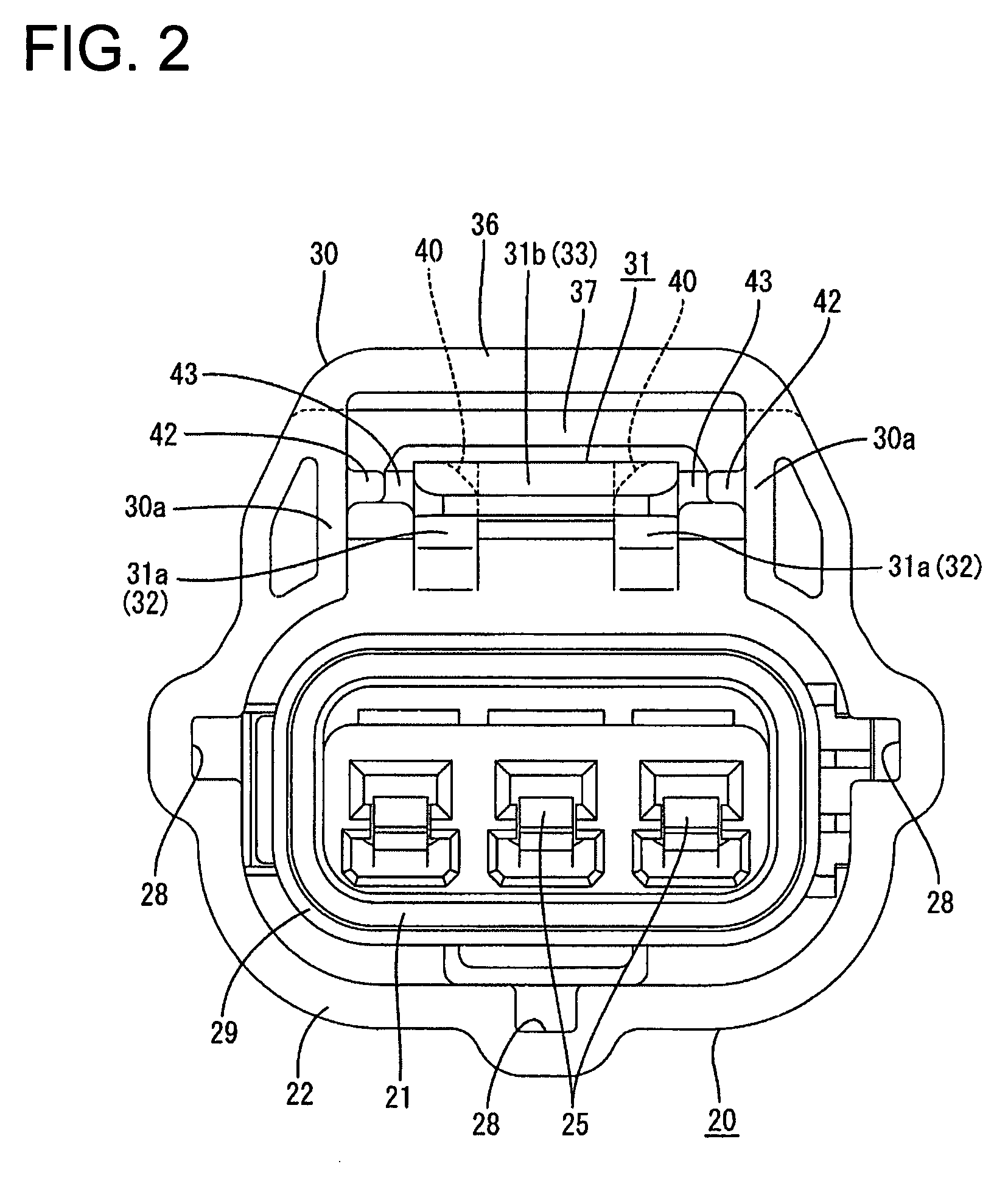
[0031]A connector in accordance with the invention is described with reference to FIGS. 1 to 13. In this embodiment the connector is fluid- or waterproof and is comprised of a male housing 10 and a female housing 20 that are connectable with each other along a connecting direction CD. Ends of the housings 10, 20 that are to be connected together are referred to herein as front ends and the opposite ends are referred to as the rear ends. Additionally, reference is made to FIGS. 1, 2 and 6 concerning the vertical direction.

[0032]The male housing 10 is made e.g. of synthetic resin and is to be connected directly with a device, such as an electric appliance, a dashboard, a junction box or the like. As shown in FIGS. 1, 4 and 6, the male housing 10 includes a terminal holding wall 11 and a receptacle 12 is connected to the outer periphery of the terminal holding wall 11. Three terminal insertion holes 11a penetrate the terminal holding wall 11 in forward and backward directions FBD and a...


PUM


Abstract

A male housing (10) has a lock (17), whereas a female housing (20) has a resiliently deformable lock arm (31) cantilevered along a connecting direction of the two housings (10, 20). The lock arm (31) deforms in the process of connecting the two housings (10, 20) and resiliently restores upon proper connection to engage the lock (17) for holding the housings (10, 20) connected. The female housing (20) has a first lock protecting wall (36) covering a side of the lock arm (31) including a free end portion (31b), and a second lock protecting wall (37) covering a side of the lock arm (31) including base end portions (31a). An unlocking space (38) between the first and second lock protecting wall (36, 37) exposes a middle part (31c) of the lock arm (31) to the outside.

Description

BACKGROUND OF THE INVENTION[0001]1. Field of the Invention[0002]The invention relates to a connector and to a connector assembly.[0003]2. Description of the Related Art[0004]Japanese Unexamined Patent Publication No. 2002-203635 discloses a connector assembly with male and female housings that can be connected together. A lock arm is cantilevered forward on the female housing and has a lock hole that engages a lock on the male housing to hold the housings together. The lock presses and deforms the lock arm in the process of connecting the housings. However, the lock arm is restored resiliently when the housings are connected properly. As a result, the lock enters the lock hole and engages the edge of the lock hole to hold the two housings together. A lock protecting portion is formed on the female housing and covers the front end of the lock arm. Thus, the lock arm cannot be caught and warped by a wire or the like before the housings are connected.[0005]The base end of the lock arm ...

Claims


Application Information

Patent Timeline
Patent Type & Authority Patents(United States)
IPC IPC(8): H01R13/627
CPCH01R13/6272
Inventor MASE, TSUYOSHITANAKA, TSUTOMU
Owner SUMITOMO WIRING SYST LTD
Why Eureka
Try Eureka