RFID device with content insensitivity and position insensitivity

a radio frequency identification and content technology, applied in loop antennas with ferromagnetic cores, instruments, burglar alarm mechanical actuation, etc., can solve the problems of low efficiency antennas, difficult to determine what is a “good” antenna, and large etc. problem, to achieve the effect of small loss resistance and relatively small radiation resistance, and not working well in most situations

Active Publication Date: 2009-03-10
AVERY DENNISON CORP
View PDF137 Cites 62 Cited by
  • Summary
  • Abstract
  • Description
  • Claims
  • Application Information

AI Technical Summary

Benefits of technology

[0026]To the accomplishment of the foregoing and related ends, the invention comprises the features hereinafter fully described and particularly pointed out in the claims. The following description and the annexed drawings set forth in detail certain illustrative embodiments of the invention. These embodiments are indicative, however, of but a few of the various ways in which the principles of the invention may be employed. Other objects, advantages and novel features of the invention will become apparent from the following detailed description of the invention when considered in conjunction with the drawings.

Problems solved by technology

However, there are some practical constraints on what designs can be used with RFID tags and labels.
Nevertheless, even given the above, it is difficult to determine what is a “good” antenna, other than to require that it is one that does what you want, where you want and is built how you want it to be.
A low efficiency antenna, with a large loss resistance and relatively small radiation resistance, will not work well in most situations, as the majority of any power put into it will simply appear as heat and not as useful electromagnetic waves.
In addition, high Q / narrow band matching solutions are unstable, in that very small variations in component values or designs will cause large changes in performance.
However, sometimes it is not so simple to meet operational demands for the tag due to environmental or manufacturing constraints, and then other ways of achieving a good match must be considered.
These components do not normally include resistors, as these dissipate energy, which will generally lead to lower performance.
Difficulties can arise in impedance matching, because the impedance characteristics of an antenna may be affected by its surroundings.
This may in turn affect the quality of the impedance matching between the antenna and the RFID chip, and thus the read range for the RFID tag.
However, individual tuning of antennas would not be practical from a business perspective.
For example, a label having a dipole antenna designed and optimized for free space that is instead attached to an object having a dielectric constant that differs from that of free space, will suffer a degraded performance, usually manifesting itself as reduced operational range and other inefficiencies as discussed above.
Therefore, while products having differing fixed dielectric constant substrates can be accommodated by changing the antenna design from the ‘free space’ design to incorporate the new dielectric constant or to compensate for other objects expected to be nearby the tag, this design change forces the tag manufacturer to produce a broader range of labels or tags, potentially a different type for each target product for which the tag may be applied, hence increasing costs and forcing an inventory stocking problem for the tag manufacturers.

Method used


Image

  • RFID device with content insensitivity and position insensitivity
  • RFID device with content insensitivity and position insensitivity
  • RFID device with content insensitivity and position insensitivity

Examples


Embodiment Construction

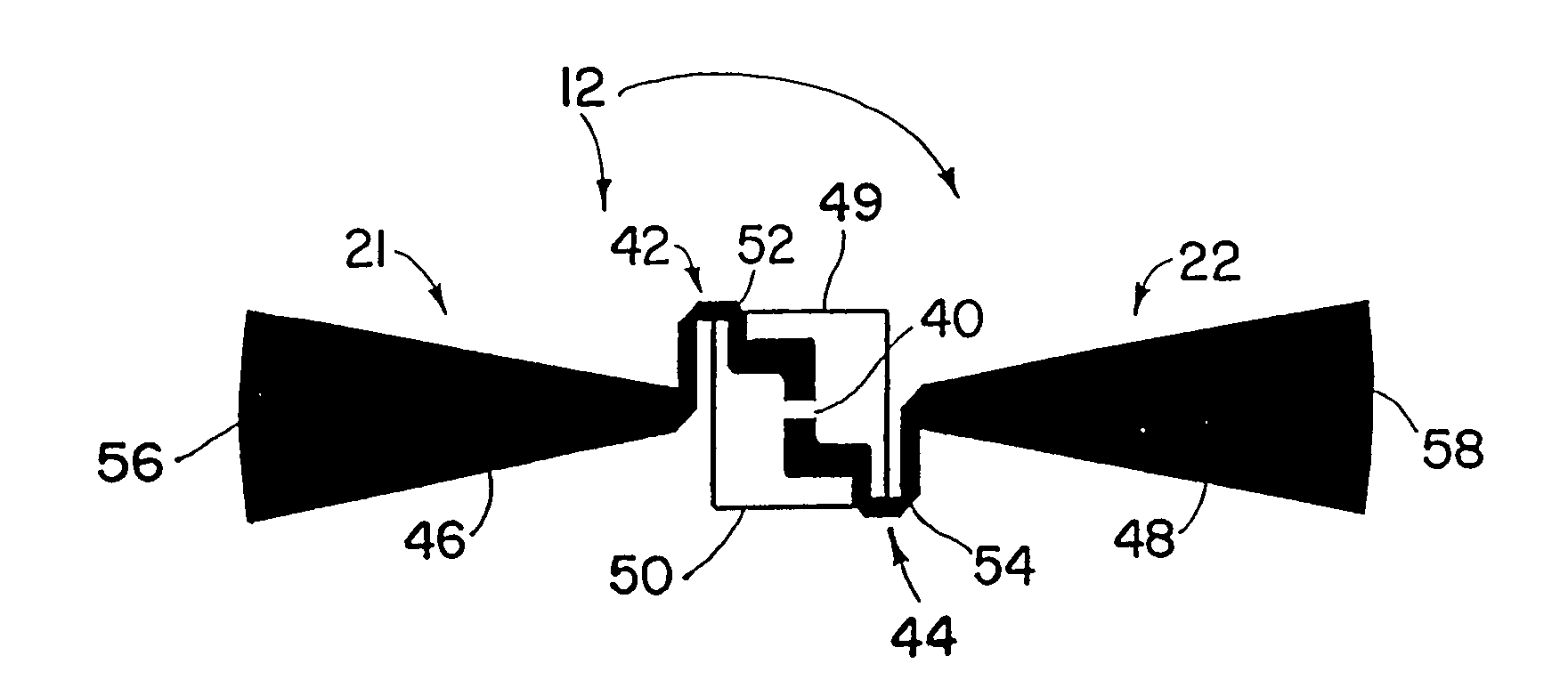
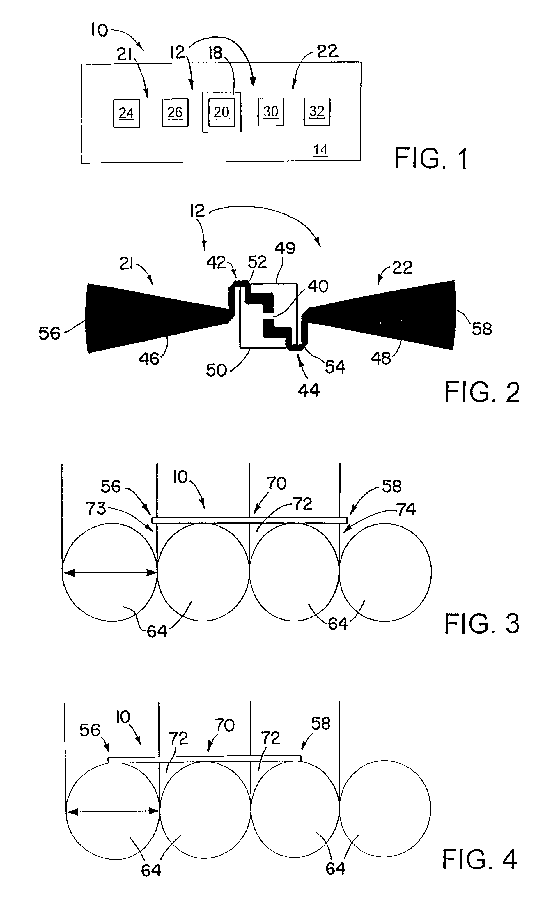
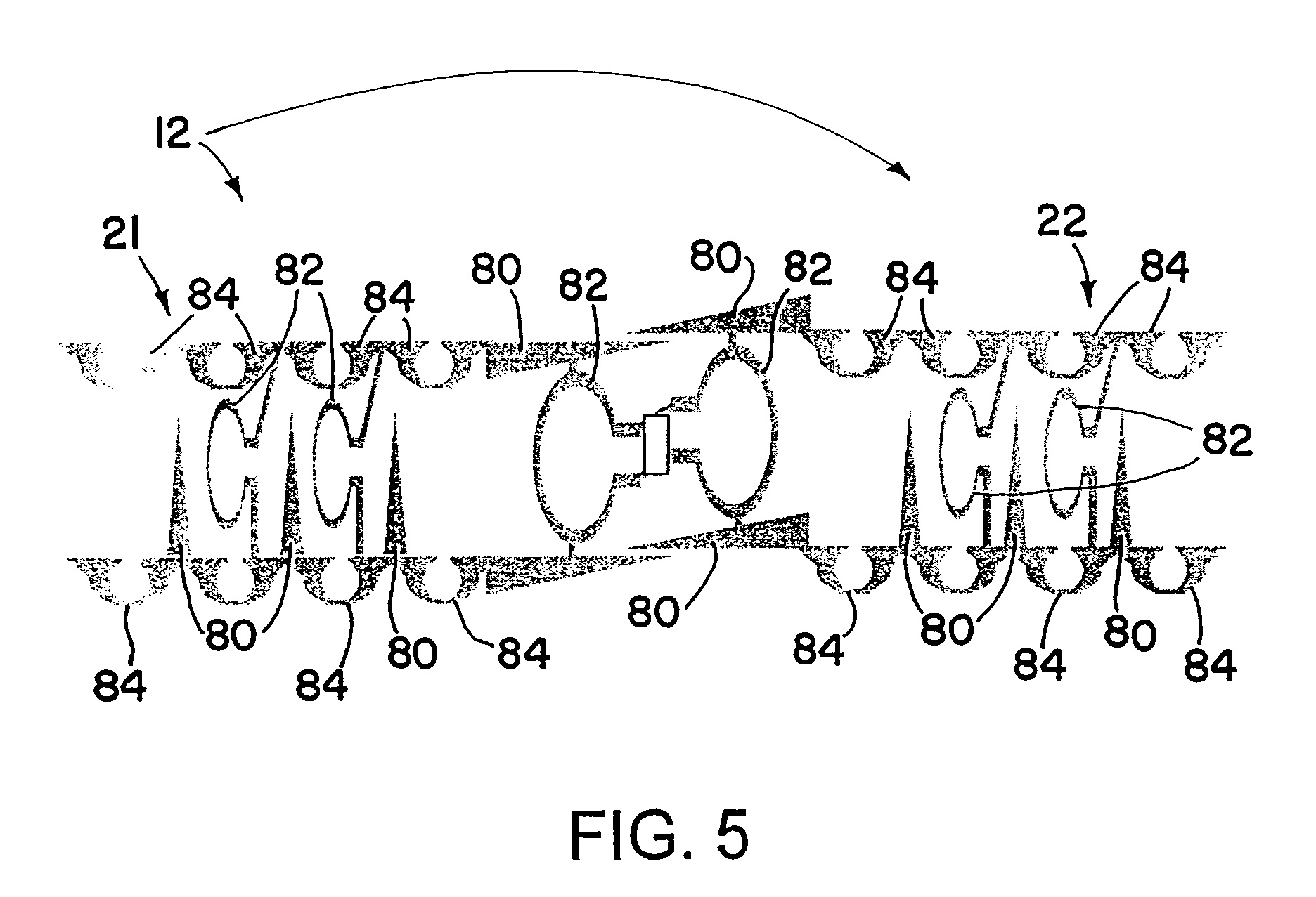
[0049]An RFID device includes an antenna structure that provides good performance throughout a range of different positions relative to nearby materials, such as metallic objects in a carton or other container. The antenna structure has compensation elements that interact with the nearby materials to provide good performance over the range of different positions. The compensation elements include both electrical compensation elements, which interact with the nearby materials primarily using electric fields, and magnetic compensation elements, which interact with the nearby materials primarily using magnetic fields. The electrical compensation elements and the magnetic compensation elements may be selected and may be positioned within the antenna structure such that the performance of the antenna structure is substantially unchanged (or at least acceptable) through the range of different positions. The nearby materials may include dielectric and / or electrically conductive materials t...


PUM


Abstract

An RFID device includes an antenna structure that provides good performance throughout a range of different positions relative to nearby materials, such as metallic objects in a carton or other container. The antenna structure has compensation elements that interact with the nearby materials to provide good performance over the range of different positions. The compensation elements include both electrical compensation elements, which interact with the nearby materials primarily using electric fields, and magnetic compensation elements, which interact with the nearby materials primarily using magnetic fields. The electrical compensation elements and the magnetic compensation elements may be selected and may be positioned within the antenna structure such that the performance of the antenna structure is substantially unchanged (or at least acceptable) through the range of different positions.

Description

[0001]This application claims priority from U.S. Provisional Application No. 60 / 609,375, filed Sep. 13, 2004.BACKGROUND OF THE INVENTION[0002]1. Field of the Invention[0003]This invention relates to the field of radio frequency identification (RFID) tags and labels.[0004]2. Description of the Related Art[0005]RFID tags and labels have a combination of antennas and analog and / or digital electronics, which may include for example communications electronics, data memory, and control logic. RFID tags and labels are widely used to associate an object with an identification code. For example, RFID tags are used in conjunction with security-locks in cars, for access control to buildings, and for tracking inventory and parcels. Some examples of RFID tags and labels appear in U.S. Pat. Nos. 6,107,920, 6,206,292, and 6,262,292, all of which this application incorporates by reference.[0006]RFID tags and labels include active tags, which include a power source, and passive tags and labels, whic...

Claims


Application Information

Patent Timeline
Patent Type & Authority Patents(United States)
IPC IPC(8): G08B13/14H01Q7/08H01Q9/16H01Q5/48
CPCG06K19/07749H01Q1/22H01Q1/2208H01Q5/48H01Q1/38H01Q9/285H01Q1/2225G06K19/07G06K19/077
Inventor FORSTER, IAN J.FARR, ADRIAN N.
Owner AVERY DENNISON CORP
Why Eureka
Try Eureka