
Antenna device and radio communication apparatus using the same

a radio communication apparatus and antenna technology, applied in the field of antenna devices and radio communication apparatus using the same, can solve the problems of reducing the gain (sensitivity) of the signals in the frequency band for telecasts, affecting the operation of the antenna, so as to achieve the effect of preventing interferen

Inactive Publication Date: 2009-03-10
MURATA MFG CO LTD
View PDF25 Cites 13 Cited by
  • Summary
  • Abstract
  • Description
  • Claims
  • Application Information

AI Technical Summary

Benefits of technology

The present invention provides a compact antenna device that can prevent interference between signals in different frequency bands, and a radio communication apparatus using the same. The antenna device includes a tunable receiving antenna that can change the frequency band for reception, and a signal-band separating circuit that compensates for the sensitivity of the tunable receiving antenna in the frequency band for reception. The antenna device and the radio communication apparatus are small in size and can provide high-quality antenna operation.

Problems solved by technology

The entrance of the signals in the frequency band for communication presents problems of reduction in gain (sensitivity) of the signals in the frequency band for telecasts and degradation of antenna characteristics.
However, it is difficult to appropriately transmit and receive signals in a wide frequency range including the frequency band for telecasts and the frequency band for communication using only one antenna.
However, it is difficult to properly transmit and receive signals of all channels in such a wide frequency range using only one antenna.
Furthermore, when the antenna is configured both to transmit and receive the signals in the frequency band for communication and to receive the signals in the frequency band for telecasts, the size of the antenna 90 increases, and the apparatus (antenna device) cannot be made compact.

Method used


Image

  • Antenna device and radio communication apparatus using the same
  • Antenna device and radio communication apparatus using the same
  • Antenna device and radio communication apparatus using the same

Examples


Embodiment Construction

[0030]Preferred embodiments of the present invention will now be described with reference to the drawings.

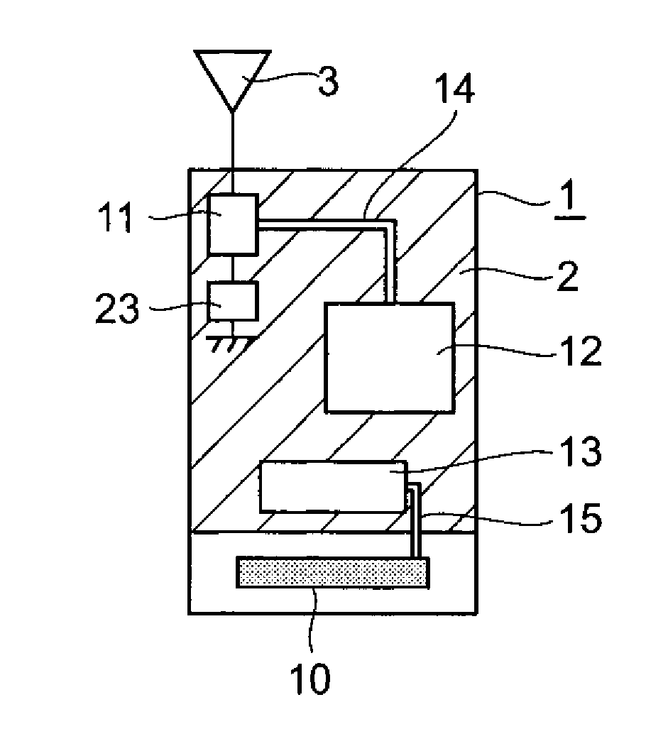
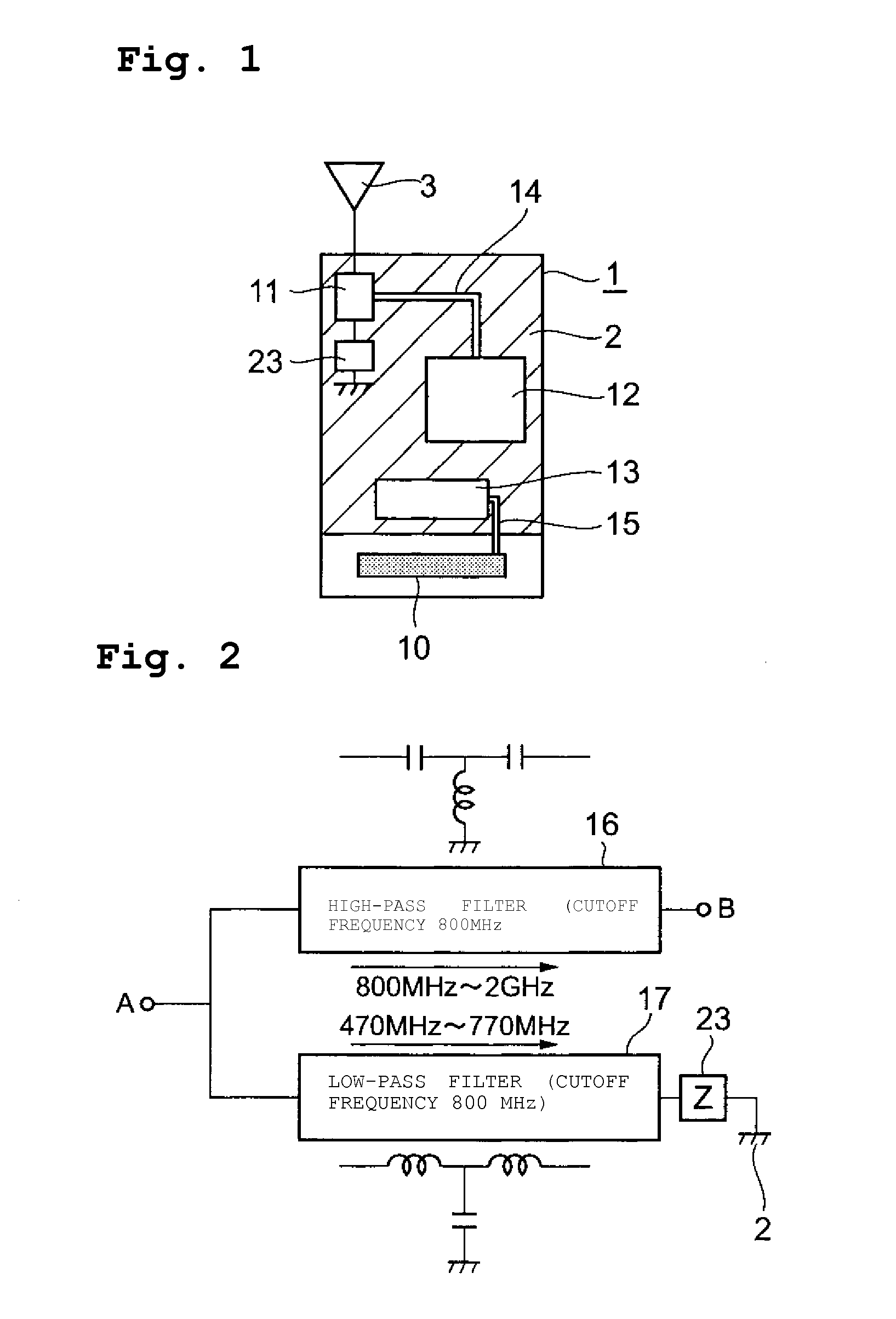
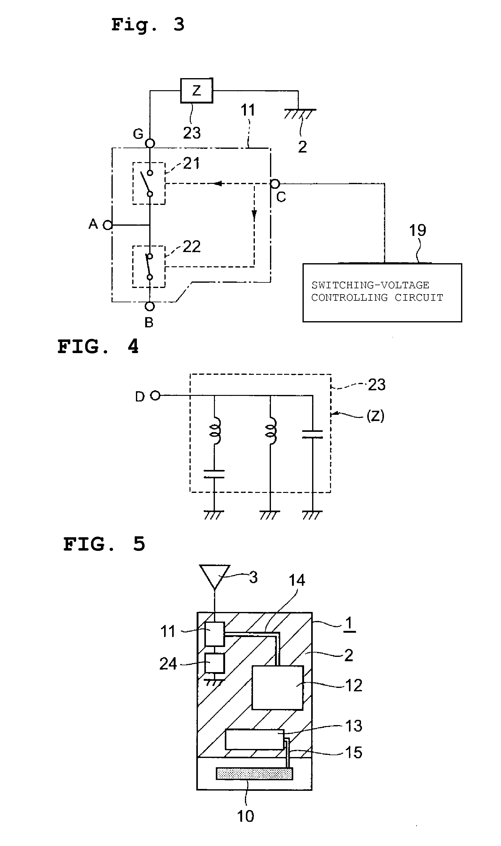
[0031]FIG. 1 illustrates an antenna device according to a first preferred embodiment of the present invention. In FIG. 1, a circuit board 1 includes an information transmitting / receiving antenna 3 for telephone calls (also referred to as a communication antenna 3 hereafter), a signal-band separating circuit 11, a reactance circuit 23, a ground portion 2, a signal line 14 defined by a conductive pattern, a communication circuit 12, a broadcast circuit 13, a signal line 15 defined by a conductive pattern, and a telecast-receiving antenna (broadcast antenna) 10 defined by a tunable receiving antenna. The communication antenna 3 is a type that protrudes from the circuit board 1 toward the outside. The protruding type includes, for example, whip antennas, helical antennas, and other suitable antennas. However, the communication antenna 3 may also be an embedded type. The signal-band ...


PUM


Abstract

An antenna device includes a signal-band separating circuit that is interposed between a communication antenna and a ground portion that are disposed on a circuit board. The communication antenna is connected to a communication circuit by a signal line via a signal-band separating circuit. A telecast-receiving antenna is connected to a broadcast circuit by a signal line. The signal-band separating circuit transmits signals in a frequency band for communication between the communication antenna and the communication circuit, and transmits signals in a frequency band for telecasts between the communication antenna and the ground portion. The antenna length (electrical length) of the telecast-receiving antenna is extended by adding the antenna length of the communication antenna in addition to the antenna length of the ground portion, thereby improving the antenna gain during telecast reception.

Description

BACKGROUND OF THE INVENTION[0001]1. Field of the Invention[0002]The present invention relates to antenna devices capable of transmitting / receiving information and capable of receiving broadcasts such as telecasts, and to radio communication apparatuses including such antenna devices.[0003]2. Description of the Related Art[0004]Cellular phones are in widespread use as radio communication apparatuses for transmitting and receiving information. Recently, cellular phones capable of receiving, visualizing, and auralizing telecasts have been proposed. Antenna devices capable of both communication (telephone calls) and telecast reception may have a structure as shown in FIG. 10.[0005]An antenna device shown in FIG. 10 includes an antenna 90 capable of both receiving signals in a frequency band for telecasts and transmitting / receiving signals in a frequency band for telephone calls (communication). The antenna 90 is mounted on a circuit board 100. A branching filter 80, a communication circ...

Claims


Application Information

Patent Timeline
Patent Type & Authority Patents(United States)
IPC IPC(8): H04M1/00H01Q1/24H01Q1/48H01Q21/28H04B1/38
CPCH01Q1/242H04B1/3805H04B1/3833
Inventor SHIMIZU, MIEKAWAHATA, KAZUNARI
Owner MURATA MFG CO LTD
Learn More