
Tightening indicator for coaxial cable connector

a technology of tightening indicator and coaxial cable, which is applied in the direction of coupling device connection, two-pole connection, two-part coupling device, etc., and can solve problems such as signal leakage, intermittent grounding, and affecting the service of all subscribers

Active Publication Date: 2009-03-24
PPC BROADBAND INC
View PDF18 Cites 164 Cited by
  • Summary
  • Abstract
  • Description
  • Claims
  • Application Information

AI Technical Summary

Benefits of technology

The patent describes a coaxial cable connector that has a visible indicator when it is fully screwed onto an equipment port. The connector includes an outer body, inner body, post, threads, shoulder, spring, compression sleeve, and indicator. When the connector is not fully screwed onto the equipment port, the indicator is not visible, but when it is fully screwed, the indicator extends outward beyond the edge of the outer body, making it easy for users to see. This design ensures that users can easily identify when the connector is fully screwed onto the equipment port, which improves the overall reliability and performance of the connector.

Problems solved by technology

Because all the return signals funnel back into the headend, a single source of unwanted RF interference (RFI), also known as “ingress”, affects the service of all the subscribers.
The RFI enters the system from improperly installed F-connectors, cracked or improperly shielded coaxial cable, or simply bad shielding around a television set's tuner.
Improper installation includes the failure to tighten fully the connector into an equipment port, thus causing signal leakage and intermittent grounding.
Cable operators are spending enormous amounts of money and resources to maintain the headend plant free from the RFI caused by loose and improper connections.
Small levels of ingress can disrupt voice service or cause dropped calls.

Method used


Image

  • Tightening indicator for coaxial cable connector
  • Tightening indicator for coaxial cable connector
  • Tightening indicator for coaxial cable connector

Examples


Embodiment Construction

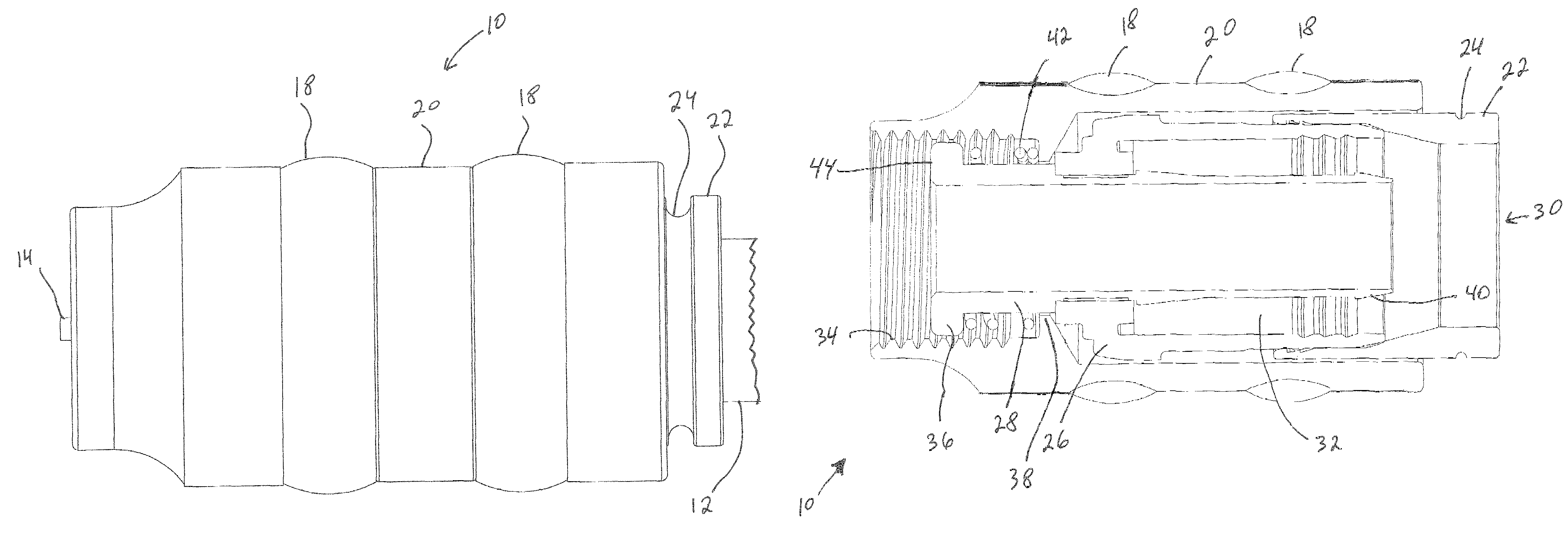
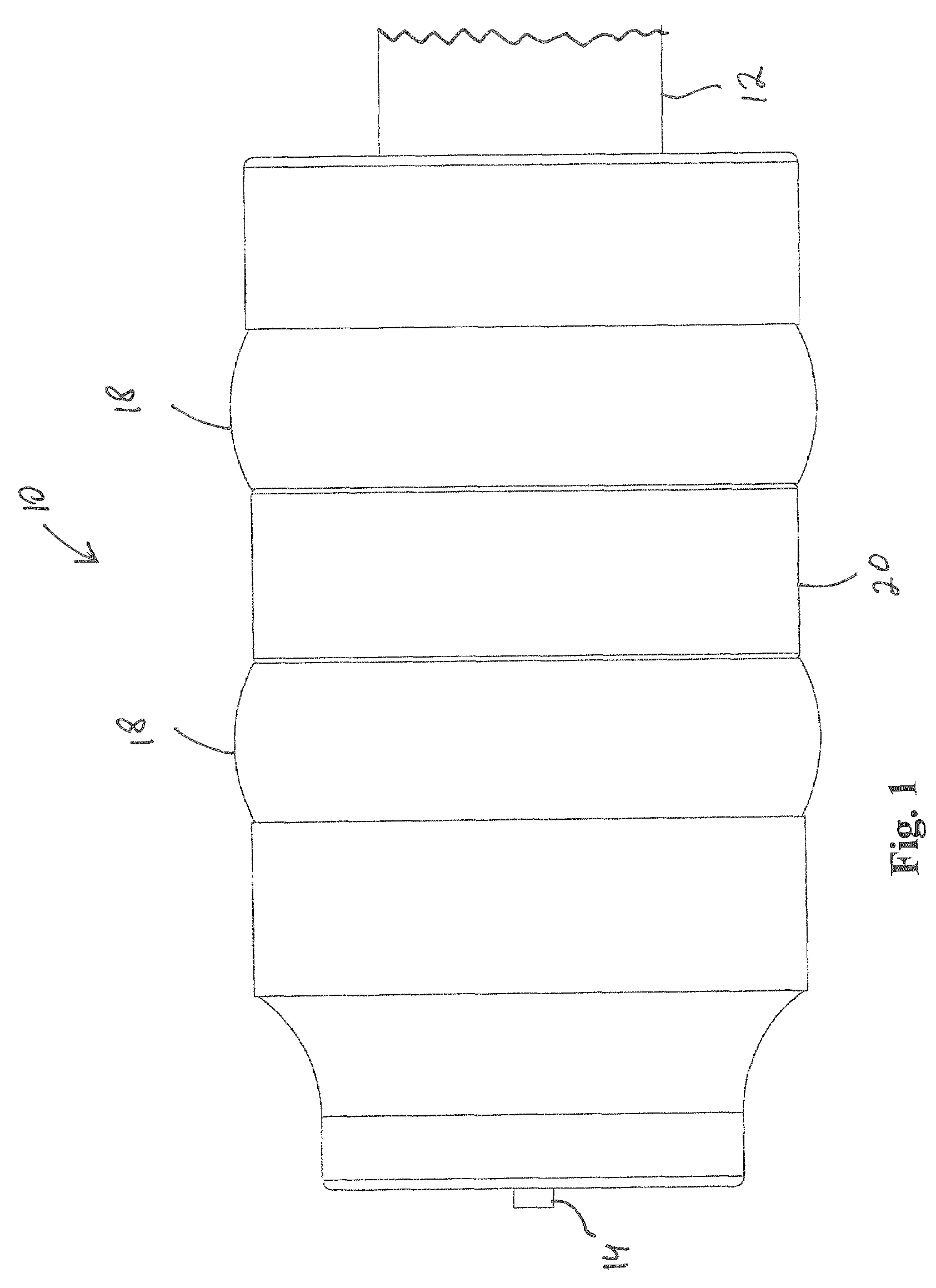
[0012]Referring to FIG. 1, a coaxial cable connector according to an embodiment of the invention is shown. Connector 10 is shown connected to a coaxial cable 12, which connection leaves a center conductor 14 of coaxial cable 12 positioned to make contact with a signal input (not shown) of an equipment port (not shown) when connector 10 is connected into the equipment port. A plurality of elastomeric rings 18 are preferably around parts of outer body 20. Elastomeric rings 18 increase the ease of tightening connector 10 to the equipment port. Connector 10 is shown in an un-tightened state, that is, connector 10 is not screwed onto the equipment port.

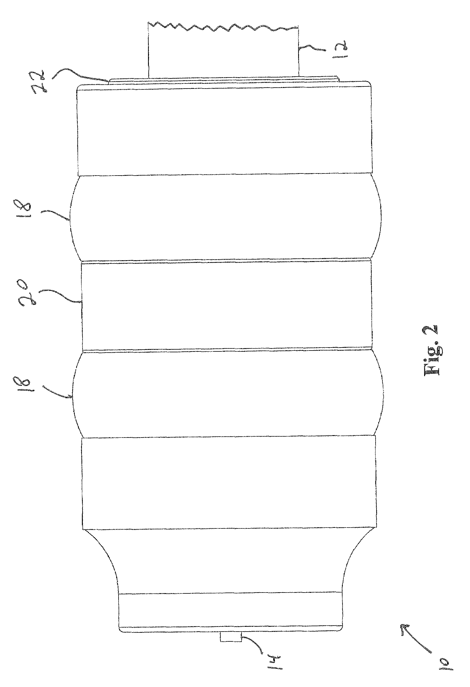
[0013]Referring to FIG. 2, connector 10 is shown in either a partially tightened state according to one embodiment of the invention, or in a fully tightened state in another embodiment of the invention. Part of a compression sleeve 22 is now visible as it extends past outer body 20.

[0014]Referring to FIG. 3, a groove 24 in compression slee...


PUM


Abstract

A coaxial cable connector includes an outer body, an inner body, a post interconnected with the inner body, a plurality of threads inside a first end of the outer body, and a compression sleeve disposed to fit between a second end of the outer body and an end of the inner body. The connector further includes a shoulder on an end of the post, a shoulder on an inside of the outer body, and a spring disposed between the shoulder of the post and the shoulder of the outer body. When the connector is not is not screwed completely onto an equipment port, a visible indicator on the compression sleeve is not visible to a user, but when the connector is screwed completely onto the equipment port, the connector becomes visible to the user.

Description

FIELD OF THE INVENTION[0001]This invention relates generally to the field of coaxial cable connectors, and more particularly to a coaxial cable connector with a visual indicator showing when the connector is fully tightened onto an equipment port.BACKGROUND OF THE INVENTION[0002]With CATV (cable television) technology, it is extremely important to ensure that all connections are tight in order to prevent unwanted interference from getting into the transmission path. For bidirectional systems, it has been estimated that 70%-95% of the unwanted RF interference on the return path, from the subscriber to the headend, originates within the subscriber's premises or home. Because all the return signals funnel back into the headend, a single source of unwanted RF interference (RFI), also known as “ingress”, affects the service of all the subscribers. The RFI enters the system from improperly installed F-connectors, cracked or improperly shielded coaxial cable, or simply bad shielding around...

Claims


Application Information

Patent Timeline
Patent Type & Authority Patents(United States)
IPC IPC(8): H01R9/05
CPCH01R24/40H01R13/622Y10T29/5193H01R2103/00
Inventor AMIDON, JEREMY
Owner PPC BROADBAND INC
Learn More