
Scheduling of automated tests in a telecommunication system

a technology for telecommunication systems and automated testing, applied in substation equipment, electrical equipment, surveillance/monitoring/testing arrangements, etc., can solve the problems of prior art scheduling techniques that have failed to meet the foregoing goals, and the trunk circuit is unavailable to carry any customer calls, so as to minimize the total time required to complete testing, avoid conflict of resource assignments, and maximize the use of available testing resources

Inactive Publication Date: 2009-03-24
SPRINT CORPORATION
View PDF8 Cites 9 Cited by
  • Summary
  • Abstract
  • Description
  • Claims
  • Application Information

AI Technical Summary

Benefits of technology

[0007]The present invention generates a testing schedule that maximizes the use of available testing resources and minimizes the total time required to complete testing while avoiding conflicts in resource assignments and without compromising quality of service when testing is being conducted. The present invention achieves testing of all trunk circuits in a 50-switch long distance network within three days.

Problems solved by technology

Each test typically involves a test call being placed over the trunk circuit, which results in that trunk circuit being unavailable to carry any customer calls during the test.
Due to the complexity of the network interactions and the large number of permutations of potential testing events, prior art scheduling techniques have failed to meet the foregoing goals.
Prior art manual scheduling methods have only managed to test about 15% of a 50-switch long distance network in a two week time period.

Method used


Image

  • Scheduling of automated tests in a telecommunication system
  • Scheduling of automated tests in a telecommunication system
  • Scheduling of automated tests in a telecommunication system

Examples


Embodiment Construction

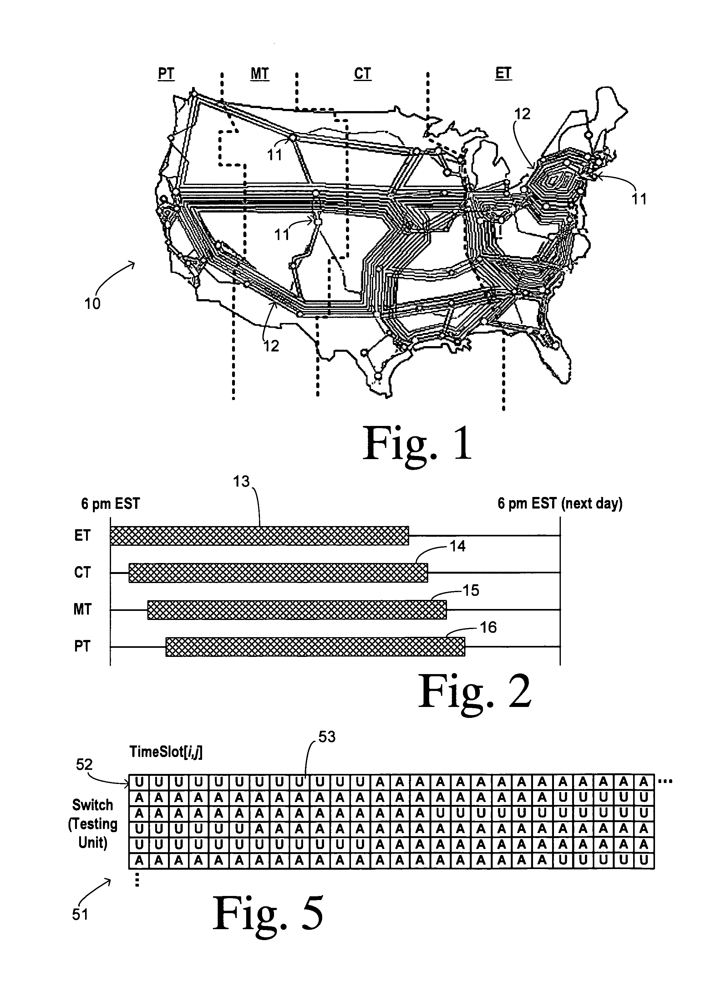
[0016]FIG. 1 shows a topology for a long distance telephone network 10 including a plurality of switches 11 shown as small circles interconnected by a plurality of trunk groups 12 in the form of fiber optic cables, for example. Network 10 spans the continental United States and its four time zones so that opposite ends of many tandem connections between switches lie in different time zones. Testing of these trunk groups results in tests between testing units that are on different local times. Thus, many tests have to accommodate two different maintenance windows.

[0017]FIG. 2 illustrates offset maintenance windows as referenced to an absolute time. For example, a maintenance window may be defined in local time from 6:00 p.m. on one day to 10:00 a.m. the next day, thereby avoiding the times of highest network demand. A maintenance window 13 is shown for a switch located in the Eastern time zone. Maintenance windows 14, 15, and 16 (established in local time from 6:00 p.m. to 10:00 a.m....


PUM


Abstract

Automated tests are scheduled for a telecommunication network. A time slot array is created and a subset of the time slots are marked as unavailable according to respective maintenance windows. A remainder of the time slots are marked as available. Trunk groups are sequentially selected for respectively scheduling the tests. A particular available time slot is identified in the array for both of the testing units corresponding to the respective trunk group. The slot is marked as unavailable and then each trunk circuit is sequentially selected within the respective trunk group. A respective test is designated for a selected trunk circuit during the particular time slot and a counter is incremented. A check is made whether the counter indicates that a number of the tests have been scheduled that fills a capacity of the testing units for running simultaneous tests. If the capacity is not filled, then the method repeats the designating step for a next selected trunk circuit using the particular time slot. Otherwise, a further time slot marked as available in the array for both of the testing units is found, the further time slot is marked as unavailable, and the designating step is repeated for a next selected trunk circuit using the further time slot.

Description

CROSS REFERENCE TO RELATED APPLICATIONS[0001]Not Applicable.STATEMENT REGARDING FEDERALLY SPONSORED RESEARCH[0002]Not Applicable.BACKGROUND OF THE INVENTION[0003]The present invention relates in general to maintenance testing of telecommunications network equipment, and, more specifically, to scheduling of tests between large numbers of network nodes using test equipment having multiple channels for conducting a plurality of simultaneous tests.[0004]In order to maintain a high level of quality of service in a telecommunications network, various standard equipment tests have been defined such as those in the Telcordia standard GR-822. In order to quickly identify all malfunctions that may compromise the quality of service, automated testing needs to be thorough and efficient so that all network resources are checked in the least amount of time. A typical telecommunications network has many functioning elements connected in a complex architecture. A nationwide long distance network, f...

Claims


Application Information

Patent Timeline
IPC IPC(8): H04M1/24H04M3/08H04M3/22
CPCH04M3/32H04M2201/14
Inventor YU, XINHUAMETTERS, DAHL BROUGHAMWATSON, VINCENT PERRY
Owner SPRINT CORPORATION
Learn More