Inflatable dunnage bags and methods for using and making the same

a bag and dunnage technology, applied in the field of inflatable packing materials, can solve the problems of difficult development of a low-cost and efficient method and structure for inflating such bags, inconvenient positioning, and inability to meet the needs of customers, etc., and achieve the effect of convenient and consistent positioning method

Inactive Publication Date: 2009-03-31
SEALED AIR U S
View PDF15 Cites 10 Cited by
  • Summary
  • Abstract
  • Description
  • Claims
  • Application Information

AI Technical Summary

Benefits of technology

[0010]The features of the present invention address the above problems and provide a novel valve assembly, inflatable dunnage bag and associated methods. The valve assembly includes a backing plate which may include a projection, such as a hook, that provides an easy and consistent method of positioning the valve assembly within a container. The backing plate may also be configured to bias the valve assembly against an inner surface of a wall of the container. Biasing the valve assembly against the inner surface allows for an inflation nozzle to puncture through the wall of the container and the front side of the valve assembly without the need to separately adhere the valve assembly to the inner surface of the wall of the container. In order to help protect the back of the valve assembly from the inflation nozzle, the backing plate may include a flap that moves the back wall away from the nozzle during insertion. Also, the backing plate may be configured for flexibility in order to compensate for changes in the shape of the valve assembly during the inflation process.
[0011]Specifically, according to an embodiment of the present invention, the inflatable dunnage bag includes a bag portion, a valve assembly, and a backing plate. The valve assembly is connected to the bag portion for allowing an inflation process to inflate the bag portion. The backing plate has an upper portion that is foldable in a first direction and a lower portion. Folding the upper portion in the first direction encourages the lower portion to bias at least a portion of the valve assembly in a second direction which aids in the inflation process. The backing plate may comprise a resilient material.
[0013]The backing plate may further have a projection for positioning the valve assembly. For example, the backing plate may have a hook that extends beyond the front wall and the back wall. The backing plate may also have a break in the material for added flexibility.
[0017]The method may also include a step of closing the container prior to inflating the bag portion. The valve assembly may include a flap which is engaged by the inflation nozzle such that the flap moves a back wall of the valve assembly away from the inflation nozzle and helps direct the fluid flow through the internal passageway.

Problems solved by technology

For example, in the case of dunnage bags that are configured to be inflated after they are placed into the container, it has proven challenging to develop a method and a structure for inflating such bags in a low cost and efficient manner.
And the valve assemblies of such bags are often too costly and cumbersome for use in a high volume environment, such as a warehouse or distribution center.
However, such gluing is undesirable in that it requires several assembly steps including applying the glue, positioning the nozzle assembly in the desired location, and then allowing the glue to dry sufficiently to cause adhesion.

Method used


Image

  • Inflatable dunnage bags and methods for using and making the same
  • Inflatable dunnage bags and methods for using and making the same
  • Inflatable dunnage bags and methods for using and making the same

Examples


Embodiment Construction

[0033]The present invention now will be described more fully hereinafter with reference to the accompanying drawings, in which some, but not all embodiments of the invention are shown. Indeed, this invention may be embodied in many different forms and should not be construed as limited to the embodiments set forth herein; rather, these embodiments are provided so that this disclosure will satisfy applicable legal requirements. Like numbers refer to like elements throughout.

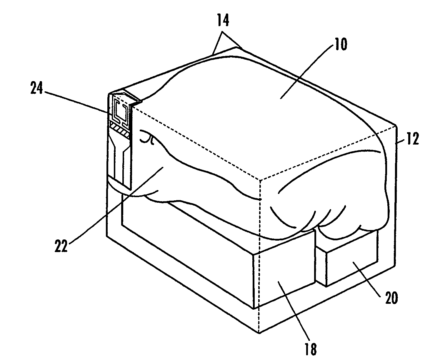
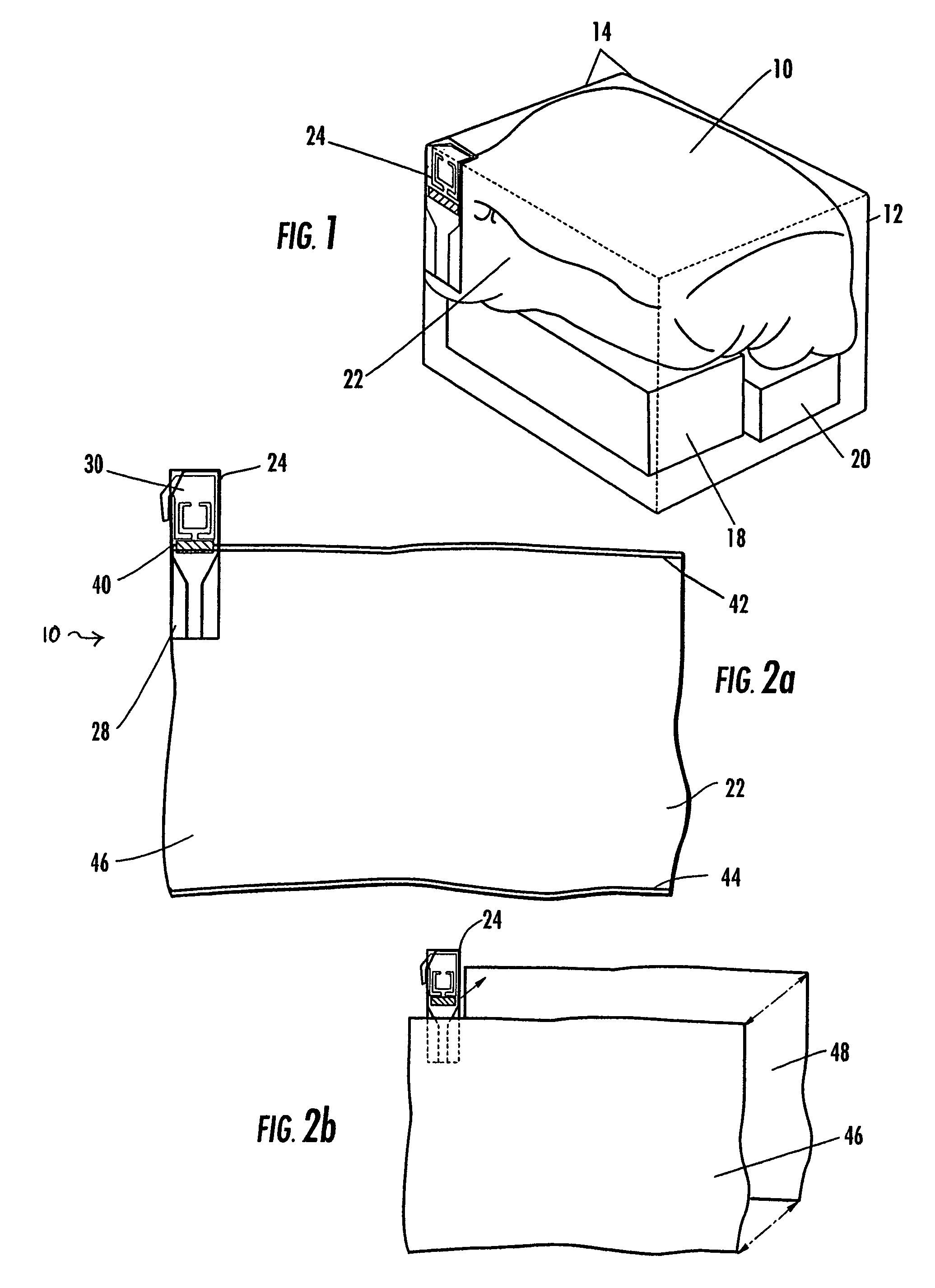
[0034]In one aspect, and as shown in FIG. 1, the present invention provides an inflatable dunnage bag 10 for filling empty space within a container 12, such as a cardboard or paperboard box. The container 12 includes walls 14 that define an interior for storing one or more items 18, 20. As shown in FIG. 2a, the inflatable dunnage bag 10 may include a bag portion 22 and a valve assembly 24. In general, the valve assembly 24 is connected to the bag portion 22 and provides an internal passageway into the bag portion ...


PUM


Abstract

An inflatable dunnage bag for filling empty space within a container is provided. The inflatable dunnage bag includes a bag portion and a valve assembly. The valve assembly is connected to the bag portion and defines a passageway through which a fluid is introduced into the bag portion during an inflation process. The valve assembly may include a backing plate, a flap, a projection, or combination thereof. The backing plate may be positioned between front and back walls of the valve assembly and be configured to protect the back wall from an inflation nozzle inserted through the front wall during the inflation process. The backing plate may include a flap adapted to further protect the back wall and help direct the fluid flow toward the bag portion. The projection, such as a hook, is configured to position the valve assembly to a predetermined area of the container.

Description

BACKGROUND OF THE INVENTION[0001]1) Field of the Invention[0002]This present invention relates generally to inflatable packing materials, such as dunnage bags.[0003]2) Description of Related Art[0004]Inflatable packing materials, such as dunnage bags, are typically used to fill void regions in containers carrying goods or items for shipment. When the dunnage bag is inflated, the items are wedged between the dunnage bag and the walls of the container or between portions of the dunnage bag. Thus the items are restricted from moving around in the container while being shipped.[0005]Dunnage bags or similar materials come in various designs, shapes and sizes. Some of them are configured to be inflated prior to placing them into the boxes or other containers as dunnage material. Others are inflated after they are placed into the container. The advantage of the latter type is that they can be inflated just enough to fill most, if not all, of the empty space that is present. Even though the...

Claims


Application Information

Patent Timeline
Patent Type & Authority Patents(United States)
IPC IPC(8): B61D45/00
CPCB31B19/84B65B55/20B65D81/052B31B2219/9067B31B70/85
Inventor SPERRY, LAURENCEPATTERSON, ROSS
Owner SEALED AIR U S
Why Eureka
Try Eureka