
Fin stabilizer to reduce roll for boats in turns method and apparatus

a technology of stabilizer and turn, applied in the direction of bilge keels, special-purpose vessels, vessel construction, etc., can solve the problems of unfavorable sharp turn, inability to properly execute the turn, and inability to stabilize the boa

Inactive Publication Date: 2009-04-07
ACBS ALUMINUM CHAMBERED BOATS
View PDF34 Cites 3 Cited by
  • Summary
  • Abstract
  • Description
  • Claims
  • Application Information

AI Technical Summary

Benefits of technology

The fin stabilization system allows for tighter turns with reduced roll, preventing chinning and maintaining a stable platform, enabling better control and safety during high-speed maneuvers, allowing gunners to maintain 'guns on target' and preventing injuries from excessive acceleration.

Problems solved by technology

When some boats having a shallow draft are making relatively sharp turns at high speeds, instability can be a problem.
Not only does this create undesired instability, but it also does not permit proper execution of the sharp turn.
This is undesirable in a situation where the boat is desired to remain in a substantially planar position about the longitudinal axis and in a situation such as where a firearm is mounted in the bow portion of the watercraft where the term, “guns on target” is necessary to complete combat operations and maneuvers.
It has been found that the trim tabs are inadequate to prevent rotation about the longitudinal axis of the vessel in particularly in high G and sharp turns which is necessary in certain maneuvers such as military maneuvers.
Trim tabs have been wholly inadequate to maintain a roll which is here in defined as rotation about the longitudinal axis of the boat.
This results in a brief period of loss of control.
When this high velocity rotation reenters the water the momentum of the propeller as well as the applied torque from the motor can cause an abrupt acceleration thereby injuring the driver and passengers of the boat (such as breaking their tailbone and ribs).
It should be noted that in the normal operations of boats, when engaging in a turn there is a de-acceleration and an excessive roll.
However, in recent times where certain combat operations necessitate a substantially lower amount of roll during turns, this excessive roll (i.e. 7-20 degrees with regard to the horizontal plane) is undesirable.
Therefore even in prior art controlled turns where the velocity is lowered and the amount of roll is such that it exceeds 20 degrees, in a military or law enforcement type operation this is undesirable.
This is clearly unacceptable if a potential target is located in this area.
It should further be noted that an excessive chinning or chine walking where the roll of the boat is so excessive that the propellers intermittedly engage causing intermittent thrust it is extremely undesirable in operations to have because this induces a lack of control where the boat is unstable and unsafe potentially causing injury to the driver and passengers.
Chinning occurs where the boat rotates at the longitudinal axis inwardly in the direction of a turn and can have catastrophic effects where in some cases a boat will rotate and snap back to the opposite direction (where the outer lateral portion of the boat violently snaps downwardly) and cause bodily injury to the passengers and driver of the boat.
Further, chinning or chine walking can compromise the boaters' abilities to engage in their missions such as firing a heavy machine gun, “bumping a boat” or maintaining a high speed pursuit.

Method used


Image

  • Fin stabilizer to reduce roll for boats in turns method and apparatus
  • Fin stabilizer to reduce roll for boats in turns method and apparatus
  • Fin stabilizer to reduce roll for boats in turns method and apparatus

Examples


Embodiment Construction

[0039]As an introductory comment, the present invention is particularly adapted for use in a boat such as shown and described in the recently issued patent, U.S. Pat. No. 6,520,107 B1, with the inventor being one of the inventors as in the present application. The entire text and drawings of U.S. Pat. No. 6,520,107 B1 are hereby incorporated by reference.

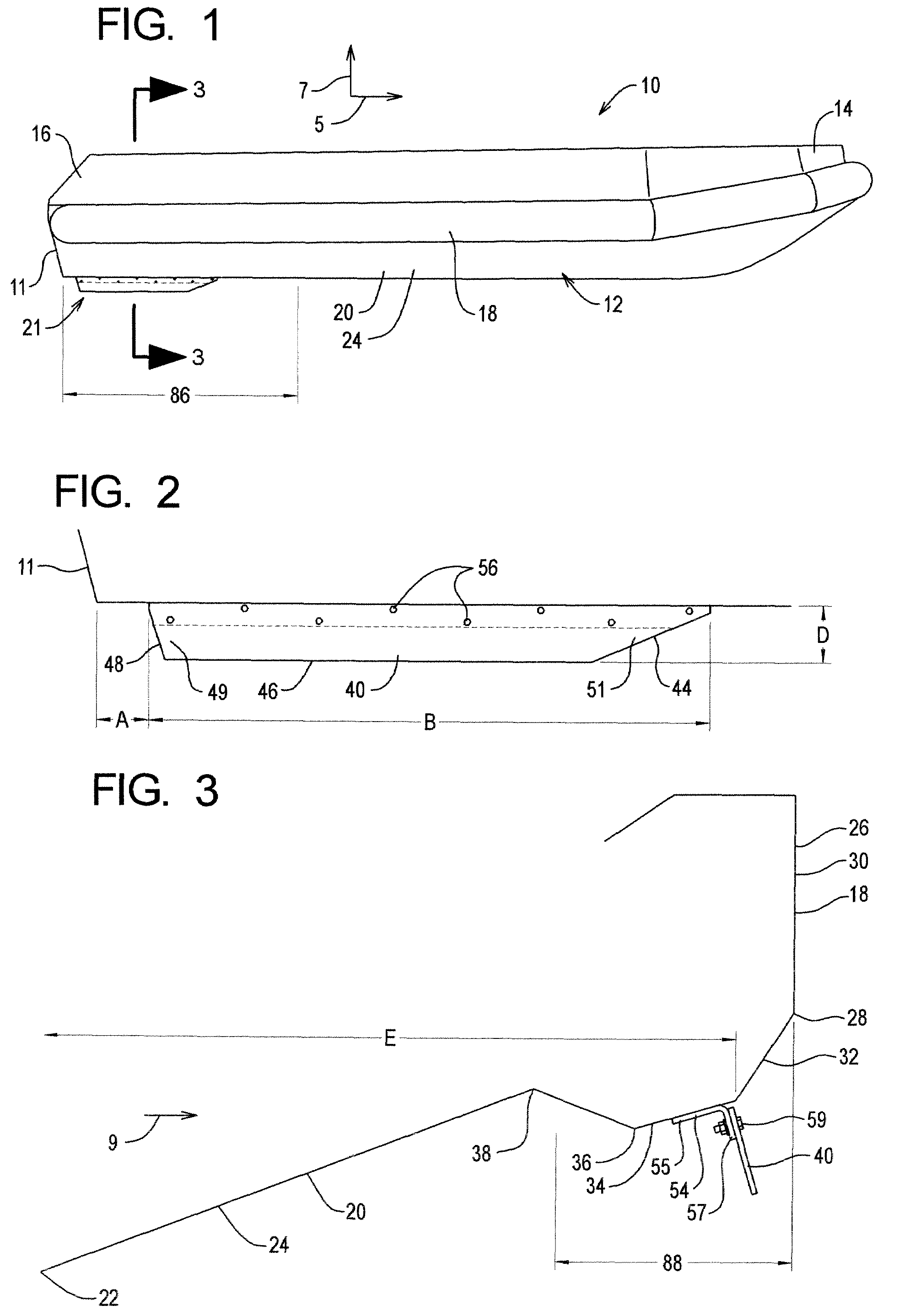
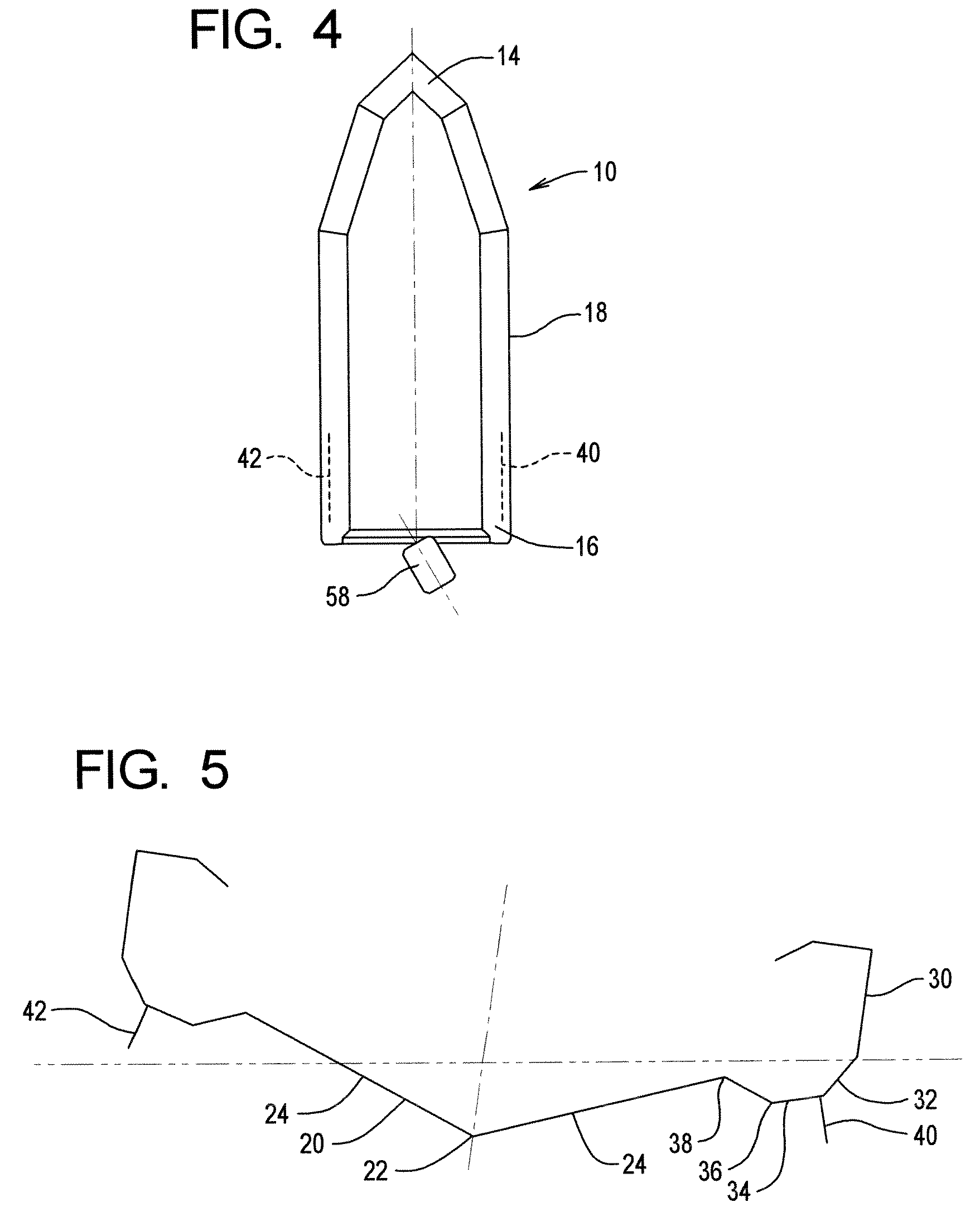
[0040]The boat 10 comprises a hull 12 having front and rear end portions 14 and 16, sidewalls 18, and a bottom wall 20. As can be seen in FIG. 5, in this particular configuration the bottom wall 20 is V-shaped so as to have a center keel 22 and two bottom wall sections 24 slanting upwardly and laterally outward at a moderate angle from the keel 22 at a moderate angle relative to the horizontal.

[0041]As is disclosed more completely in U.S. Pat. No. 6,520,107 131, the sidewall portions 18 are in this configuration made of aluminum sheets which have in cross-section a multi-creased configuration comprising planar portions 26 which conn...


PUM


Abstract

The disclosure relates to a fin stabilization system adapted to minimize roll about the longitudinal axis of the boat during sharp cornering at very high speeds. In one form, equipment such as a machine gun is mounted to the bow of the boat and targets are adapted to be engaged in high-speed maneuvers when cornering and the deck of the boat is not excessively rolled whereby blocking visibility in a turn.

Description

RELATED APPLICATIONS[0001]This application is a continuation of application Ser. No. 10 / 796,472, filed Mar. 8, 2004, now U.S. Pat. No. 7,210,422, which claims priority benefit of provisional application No. 60 / 452,710, filed Mar. 7, 2003.BACKGROUND OF THE INVENTION[0002]a) Field of the Invention[0003]The present invention relates to stabilizing systems for boats, and more particularly for a stabilizing system which better enables boats to make sharp turns, and particularly sharp turns at relatively high speeds where the roll of the boat (rotation about the longitudinal axis of the boat) is minimized.[0004]b) Background Art[0005]When some boats having a shallow draft are making relatively sharp turns at high speeds, instability can be a problem. In some instances and with some configuration of boats (if not many configurations), when the rudder or the motor is turned as to execute a sharp turn, the boat will lean into the curve / roll, with the side of the boat on the inside of the cur...

Claims


Application Information

Patent Timeline
Patent Type & Authority Patents(United States)
IPC IPC(8): B63B39/06B63B3/44
CPCB63B3/44B63B39/06
Inventor HICKOK, WILLIAM L.MORGAN, MARK R.BENSON, RICHARD MBAKER, MICHAEL A.
Owner ACBS ALUMINUM CHAMBERED BOATS
Learn More