
Low tensile creep belt

a low tensile creep and belt technology, applied in the field of belts, can solve the problems of excessive stretch and narrowness of outer fabric, premature failure of joints or seams, and excessive tensile demand on outer fabri

Inactive Publication Date: 2009-04-07
VOITH PATENT GMBH
View PDF52 Cites 11 Cited by
  • Summary
  • Abstract
  • Description
  • Claims
  • Application Information

AI Technical Summary

Benefits of technology

The solution enables the fabric to sustain high tensile loads up to 50 kN / m without stretching or seam failure, while maintaining sufficient permeability for efficient drying, achieving higher dryness levels and preventing web quality degradation.

Problems solved by technology

While this approach is effective in drying the paper, the tensile demand on the outer fabric is extremely high.
These loads are far higher than those for normal textile fabrics which may cause the outer fabric to stretch and narrow excessively and any joints or seams to fail prematurely.
However, they are too heavy and can be dangerous if they fail in operation.
In addition to that, they may not have sufficient permeability to achieve the proper drying function of the paper.

Method used


Image

  • Low tensile creep belt
  • Low tensile creep belt
  • Low tensile creep belt

Examples


Embodiment Construction

[0014]The particulars shown herein are by way of example and for purposes of illustrative discussion of the embodiments of the present invention only and are presented in the cause of providing what is believed to be the most useful and readily understood description of the principles and conceptual aspects of the present invention. In this regard, no attempt is made to show structural details of the present invention in more detail than is necessary for the fundamental understanding of the present invention, the description is taken with the drawings making apparent to those skilled in the art how the forms of the present invention may be embodied in practice.

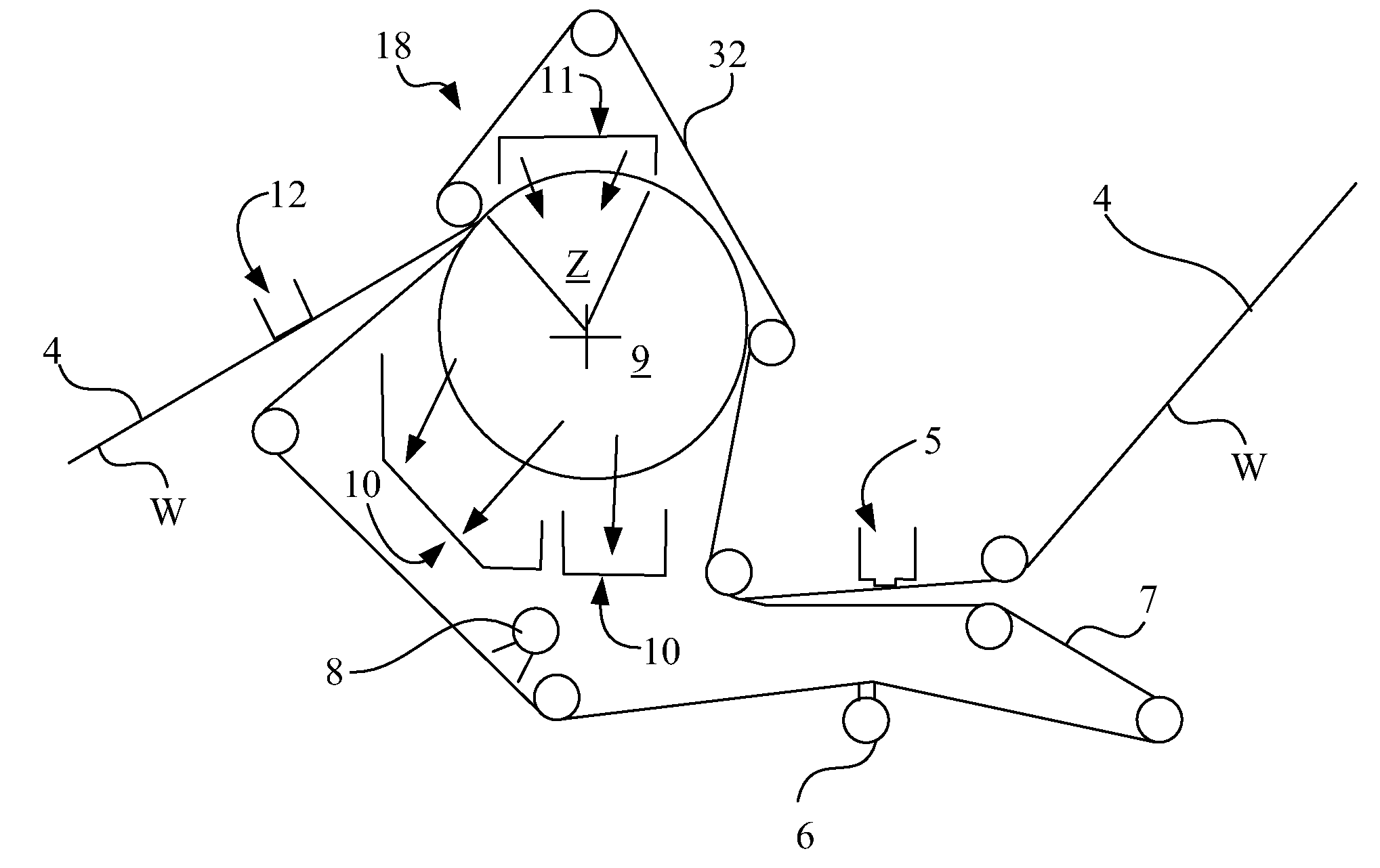
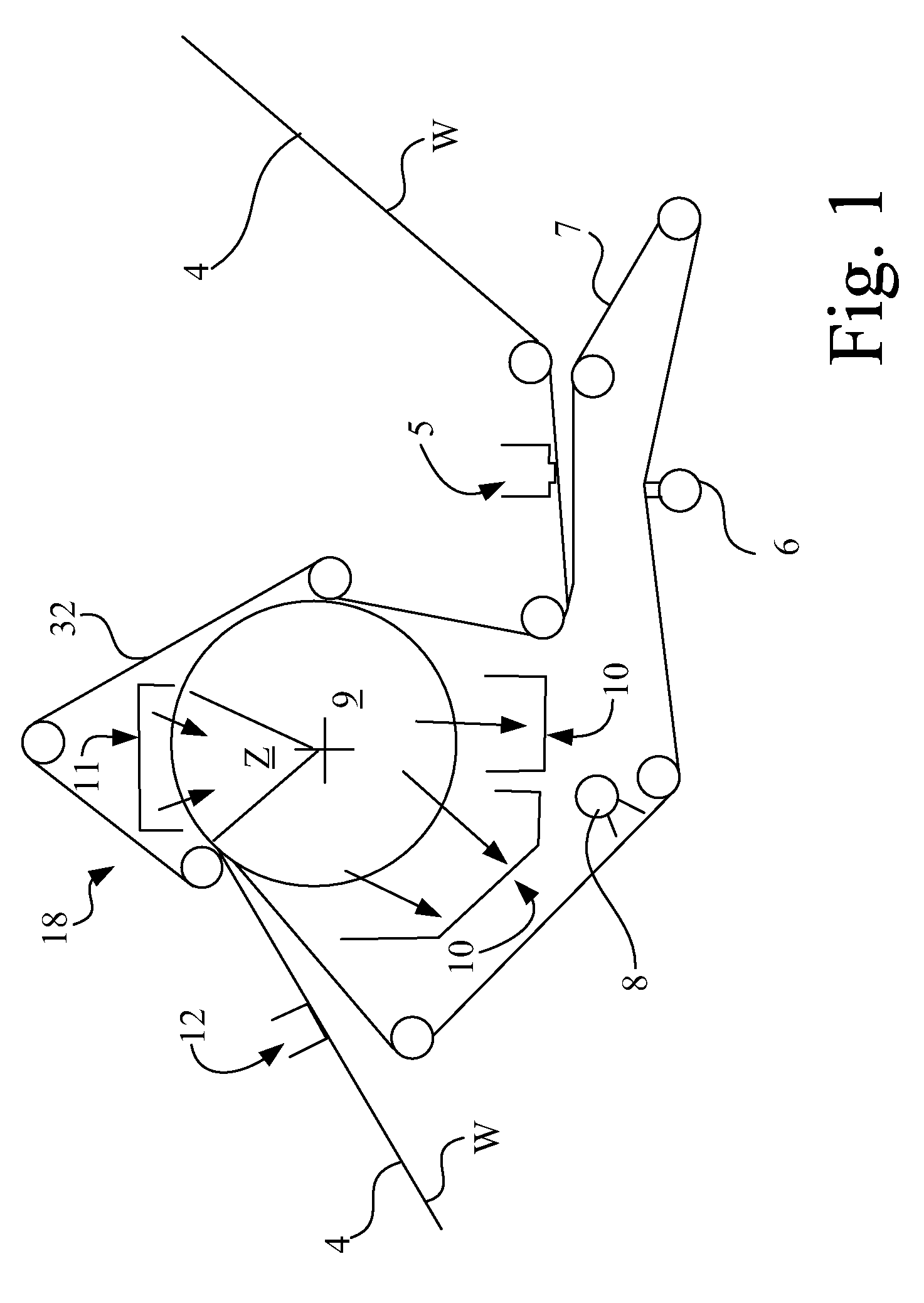
[0015]Referring now to the drawings, FIG. 1 shows a diagram of a dewatering system that utilizes a main pressure field in the form of a belt press generally indicated by reference character 18. A web W of fiber material is carried by a structured fabric 4 to a vacuum box 5 that is required to achieve a solids level of between ...


PUM


Abstract

An endless fabric belt subjected to a substantial running tension. The belt has an endless woven fabric formed from a plurality of MD (machine direction) ultra high molecular weight polymer strands approaching zero creep at high tensile loads. A plurality of CMD (cross machine direction) strands are interwoven with the MD strands. The plurality of MD strands have first and second ends spliced to one another to form an endless belt, the splices forming a significant linear MD overlap of about 30 cm with each other.

Description

BACKGROUND OF THE INVENTION[0001]1. Field of the Invention[0002]The present invention relates to belts, and, more particularly, to belts used in the paper machinery field.[0003]2. Description of the Related Art[0004]It has been found in the paper machinery art that it is possible to create a “press nip” by wrapping fabrics around a roll at high contact angles with a wet paper sheet between the fabrics. By applying high tensile load to the outer fabric, compressive forces are transmitted to the sheet and force water into the inner fabric. The advantage of this method verses a normal roll press is that the pressing zone and dwell time can be very large and the compressive force on the paper relatively low so that sheet bulk is not minimized by undue compression.[0005]The outer fabric in this arrangement, in addition to experiencing high tensile loads, must have sufficiently high permeability on the range of 100 to 600 CFM (cubic feet / min) to permit air passage through the fabric to he...

Claims


Application Information

Patent Timeline
Patent Type & Authority Patents(United States)
IPC IPC(8): D21F7/10D03D3/04D03D7/00D03D25/00
CPCD21F1/0027
Inventor CROOK, ROBERTPATEL, SANJAYZHANG, HEPINGVALENTINE, CRAIGWALKENHAUS, HUBERT
Owner VOITH PATENT GMBH
Learn More